
Pico LCD 2
| ||

Overview
This 2inch LCD display module is designed for Raspberry Pi Pico, embedded ST7789VW driver, 65K colors, 320 x 240 Pixels, equipped with SPI interface.
Features
- 320 × 240 resolution, IPS screen, 65K RGB colors, clear and colorful displaying effect.
- SPI interface requires minimal I/O pins.
- 4 x user buttons for easy interaction.
Specifications
| Parameter name | Parameters |
| Power Supply | 2.6V ~ 5.5V |
| Working Current | 40mA |
| Screen Type | IPS |
| Control Chip | ST7789V |
| Communication Interface | 4-wire SPI |
| Resolution | 240 (V) RGB x 320 (H) Pixels |
| Pixel Size | 0.0975 (H) x 0.0975 (V) (mm) |
| Display Size | 30.6 (H) x 40.8 (V) (mm) |
| Product Size | 35 (H) x 52.00 (V) (mm) |
Pinout

LCD & Controller
The built-in controller used in this LCD is ST7789VW, which is an LCD controller with 240 x 320(RGB) pixels, while the pixels of this LCD itself are 240 (H) x 320 (V)(RGB), and the internal RAM of the LCD has been fully used.
The LCD supports 12-bit, 16-bit, and 18-bit input color formats per pixel, namely RGB444, RGB565, and RGB666 three color formats, this demo uses RGB565 color format, which is also a commonly used RGB format.
The LCD uses a four-wire SPI communication interface, which can greatly save the GPIO port, and the communication speed will be faster.
Working Protocol

Note: Different from the traditional SPI protocol, since it only needs to be displayed, the data cable sent from the slave to the master is hidden, and the table is detailed in Datasheet Page 66.
RESX is the reset pin, it is pulled low when the module powers up, and is usually set to 1.
CSX is a slave chip select, when CS is low level, the chip is enabled.
D/CX is data/command control pin, when DC = 0, write command, when DC = 1, write data.
SDA is the data pin for transmitting RGB data, it works as the MOSI pin of the SPI interface.
SCL works the SCLK pins of the SPI interface.
SPI communication has data transfer timing, which is combined by CPHA and CPOL.
CPOL determines the level of the serial synchronous clock at an idle state. When CPOL = 0, the level is Low. However, CPOL has little effect on the transmission.
CPHA determines whether data is collected at the first clock edge or at the second clock edge of the serial synchronous clock; when CPHL = 0, data is collected at the first clock edge.
As can be seen from the figure, when the first falling edge of SCLK starts to transmit data, 8bit data is transmitted in one clock cycle. When using SPI0, it is transmitted by bits, that is, high bit first, low bit last.
Pico User Guide
Hardware connection
Please take care of the direction when you connect Pico/Pico2, a USB port is printed to indicate. You can also check the pin of Pico/Pico2 and the LCD board when connecting.
You can connect the display according to the table.
| LCD | Pico/Pico2 | Description |
| VCC | VSYS | Power Input |
| GND | GND | Ground |
| DIN | GP11 | MOSI pin of SPI, data transmitted from Master to Slave |
| CLK | GP10 | SCK pin of SPI, clock pin, clock signal transmitted from Master to Slave |
| CS | GP9 | Chip selection of SPI (active low) |
| DC | GP8 | Data/Command control pin (High for data; Low for command) |
| RST | GP12 | Reset pin (active low) |
| BL | GP13 | Backlight control |
| KEY0 | GP15 | User button KEY0 |
| KEY1 | GP17 | User button KEY1 |
| KEY2 | GP2 | User button KEY2 |
| KEY3 | GP3 | User button KEY3 |
Connection
Note: Please connect the module to Raspberry Pi Pico/Pico 2 as shown in the figure, do not connect them in the wrong direction.

Basic Introduction
MicroPython Series
【MicroPython】Basic Introduction and Environment Installation of Pico
【MicroPython】machine.Pin Detailed explanation of class functions
【MicroPython】machine.PWM Detailed explanation of class functions
【MicroPython】machine.ADC Detailed explanation of class functions
【MicroPython】machine.UART Detailed explanation of class functions
【MicroPython】machine.I2C Detailed explanation of class functions
【MicroPython】machine.SPI Detailed explanation of class functions
C/C++ Series
Download Demo codes
Open the Raspberry Pi terminal and run the following command:
sudo apt-get install p7zip-full
cd ~
sudo wget  https://files.waveshare.com/upload/5/5a/Pico_code.7z
7z x Pico_code.7z -o./Pico_code
cd ~/Pico_code
cd c/build/
Run the Demo codes
This guides is based on Raspberry Pi.
C Examples
- The following tutorial is for operating on Raspberry Pi, but due to the multi platform and portable nature of cmake, it can also be successfully compiled on PC, but the operation is slightly different and requires your own judgment.
Open a terminal and enter the directory of C codes:
cd ~/Pico_code/c/
Create and enter the build directory and add the SDK, where ../../pico-sdk is the directory of your SDK. There is a build in our sample program, you can enter it directly:
cd build
export PICO_SDK_PATH=... /... /.../pico-sdk
(Note: Be sure to write the right path for your own SDK)
Execute cmake to automatically generate Makefile files.
#Pico
cmake -DPICO_BOARD=pico -DPICO_PLATFORM=rp2040 ..
#Pico2
cmake -DPICO_BOARD=pico2 -DPICO_PLATFORM=rp2350 ..
Open main.c under the c folder, and you can change the routine you need. This routine can drive the display of our company's Pico series and the source code will be updated all the time. Please select the corresponding LCD or OLED test function and comment on the irrelevant functions.

Execute make to generate a executable file, the first compilation time is relatively long.
make -j9
After the compilation is complete, the uf2 file will be generated. Press and hold the button on the Pico board, connect the Pico to the USB port of the Raspberry Pi through the Micro USB cable, and release the button. After connecting, the Raspberry Pi will automatically recognize a removable disk (RPI-RP2), and copy the main.uf2 file in the build folder to the recognized removable disk (RPI-RP2).
#Pico
cp main.uf2 /media/pi/RPI-RP2/
#Pico2
cp main.uf2 /media/pi/RP2350
Python codes
Use in Windows
- 1. Press and hold the BOOTSET button on the Pico board, connect the Pico to the USB port of the computer through the Micro USB cable, and release the button after the computer recognizes a removable hard disk.
- 2. Copy the rp2-pico-20210418-v1.15.uf2 file in the python directory to the recognized removable disk (RPI-RP2).
- Pico: rp2-pico-20210418-v1.15.uf2
- Pico 2: rp2-pcio2-20240809-v1.24.0.uf2
- 3. Open Thonny IDE (Note: Use the latest version of Thonny, otherwise there is no Pico support package, the latest version under Windows is v3.3.3).
- 4. Click Tools -> Settings -> Interpreter, and select Pico and the corresponding port as shown in the figure.

- 5. File -> Open -> python/Pico-LCD-2/Pico-LCD-2.py, click to run, as shown in the following figure:

This demo provides a simple program...
Run in Raspberry Pi
- 1. The process of flashing the firmware is the same as on Windows, and you have the option of copying the .uf2 format file into the Pico/Pico2 on your PC or Raspberry Pi.
- 2. Open the Thonny IDE on the Raspberry Pi (click on the Raspberry logo -> Programming -> Thonny Python IDE) and you can view the version information at Help -> About Thonny to ensure that your version comes with Pico support package, you can also click on Tools ->Options... -> Interpreter chooses MicroPython (Raspberry Pi Pico and ttyACM0 ports).
As shown in below figure:

If your Thonny doesn't support Pico, you can update it with the following command:
sudo apt upgrade thonny
- 3. Click on File->Open...->python/Pico-LCD-2/Pico-LCD-2.py, then run the script.
Codes Analysis
C
Bottom hardware interface
We package the hardware layer for easily porting to the different hardware platforms.
DEV_Config.c(.h) in the directory:...\c\lib\Config
- Data type:
#define UBYTE   uint8_t
#define UWORD   uint16_t
#define UDOUBLE uint32_t
- Module initialize and exit:
void DEV_Module_Init(void);
void DEV_Module_Exit(void);
Note:
1.The functions above are used to initialize the display or exit handle.
- GPIO write/read:
void 	DEV_Digital_Write(UWORD Pin, UBYTE Value);
UBYTE 	DEV_Digital_Read(UWORD Pin);
- SPI write data
void DEV_SPI_WriteByte(UBYTE Value);
Upper application
For the screen, if you need to draw, display Chinese and English characters, display images, etc., these are handled by upper-level applications. Many friends have asked about graphics processing, and we provide some basic functions here. You can find the GUI in the following directory:..\c\lib\GUI\GUI_Paint.c(.h)

The fonts used can be found in the directory: RaspberryPi\c\lib\Fonts.

- Create a new image, you can set the image name, width, height, rotate angle, and color.
void Paint_NewImage(UWORD *image, UWORD Width, UWORD Height, UWORD Rotate, UWORD Color, UWORD Depth)
Parameter:
 	image: Name of the image buffer, this is a pointer;
 	Width: Width of the image;
 	Height: Height of the image;
 	Rotate: Rotate the angle of the Image;
 	Color: The initial color of the image;
 	Depth: Depth of the color
- Select image buffer: You can create multiple image properties and image buffers, and you can select each image you create.
void Paint_SelectImage(UBYTE *image)
Parameter:
 	image: The name of the image buffer, this is a pointer;
- Rotate image: You need to set the rotation angle of the image, this function should be used after Paint_SelectImage(). The angle can be 0, 90, 180, or 270.
void Paint_SetRotate(UWORD Rotate)
Parameter:
 	Rotate: Rotate the angle of the image, the parameter can be ROTATE_0, ROTATE_90, ROTATE_180, ROTATE_270.
- 【Note】After rotating, the place of the first pixel is different as below:


- Image mirror: This function is used to set the image mirror.
void Paint_SetMirroring(UBYTE mirror)
Parameter:
 	mirror: Mirror type if the image, the parameter can be MIRROR_NONE、MIRROR_HORIZONTAL、MIRROR_VERTICAL、MIRROR_ORIGIN.
- Set the position and color of pixels: This is the basic function of GUI, it is used to set the position and color of a pixel in the buffer.
void Paint_SetPixel(UWORD Xpoint, UWORD Ypoint, UWORD Color)
Parameter:
 	Xpoint: The X-axis position of the point in the image buffer
 	Ypoint: The Y-axis position of the point in the image buffer
 	Color: The color of the point
- Color of the image: To set the color of the image, this function always be used to clear the display.
void Paint_Clear(UWORD Color)
Parameter:
 	Color: The color of the image
- Color of the windows: This function is used to set the color of windows, it is always used for updating partial areas like displaying a clock.
void Paint_ClearWindows(UWORD Xstart, UWORD Ystart, UWORD Xend, UWORD Yend, UWORD Color)
Parameter:
 	Xstart: X-axis position of the start point.
 	Ystart: Y-axis position of the start point.
 	Xend: X-axis position of the endpoint.
 	Yend: Y-axis position of the endpoint
 	Color: Color of the windows.
- Draw a point: Draw a point at the position (Xpoint, Ypoint) of the image buffer, you can configure the color, size, and style.
void Paint_DrawPoint(UWORD Xpoint, UWORD Ypoint, UWORD Color, DOT_PIXEL Dot_Pixel, DOT_STYLE Dot_Style)
Parameter:
 	Xpoint: X-axis position of the point.
 	Ypoint: Y-axis position of the point
 	Color: Color of the point
 	Dot_Pixel: Size of the point, 8 sizes are available.
 	 	 typedef enum {
 	 	 	 DOT_PIXEL_1X1  = 1,	// 1 x 1
 	 	 	 DOT_PIXEL_2X2  , 		// 2 X 2
 	 	 	 DOT_PIXEL_3X3  , 	 	// 3 X 3
 	 	 	 DOT_PIXEL_4X4  , 	 	// 4 X 4
 	 	 	 DOT_PIXEL_5X5  , 		// 5 X 5
 	 	 	 DOT_PIXEL_6X6  , 		// 6 X 6
 	 	 	 DOT_PIXEL_7X7  , 		// 7 X 7
 	 	 	 DOT_PIXEL_8X8  , 		// 8 X 8
 	 	} DOT_PIXEL;
 	Dot_Style: The style of the point, defines the extended mode of the point.
 	 	typedef enum {
 	 	   DOT_FILL_AROUND  = 1,
 	 	   DOT_FILL_RIGHTUP,
 	 	} DOT_STYLE;
- Draw a line: Draw a line from (Xstart, Ystart) to (Xend, Yend) in the image buffer, you can configure the color, width, and style.
void Paint_DrawLine(UWORD Xstart, UWORD Ystart, UWORD Xend, UWORD Yend, UWORD Color, LINE_STYLE Line_Style , LINE_STYLE Line_Style)
Parameter:
 	Xstart: Xstart of the line
 	Ystart: Ystart of the line
 	Xend: Xend of the line
 	Yend: Yend of the line
 	Color: The color of the line
 	Line_width: Width of the line, 8 sizes are available.
 	 	typedef enum {
 	 	 	 DOT_PIXEL_1X1  = 1,	// 1 x 1
 	 	 	 DOT_PIXEL_2X2  , 		// 2 X 2
 	 	 	 DOT_PIXEL_3X3  ,		// 3 X 3
 	 	 	 DOT_PIXEL_4X4  ,		// 4 X 4
 	 	 	 DOT_PIXEL_5X5  , 		// 5 X 5
 	 	 	 DOT_PIXEL_6X6  , 		// 6 X 6
 	 	 	 DOT_PIXEL_7X7  , 		// 7 X 7
 	 	 	 DOT_PIXEL_8X8  , 		// 8 X 8
 	 	} DOT_PIXEL;
 	 Line_Style: Style of the line, Solid or Dotted.
 	 	typedef enum {
 	 	 	 LINE_STYLE_SOLID = 0,
 	 	 	 LINE_STYLE_DOTTED,
 	 	} LINE_STYLE;
- Draw a rectangle: Draw a rectangle from (Xstart, Ystart) to (Xend, Yend), you can configure the color, width, and style.
void Paint_DrawRectangle(UWORD Xstart, UWORD Ystart, UWORD Xend, UWORD Yend, UWORD Color, DOT_PIXEL Line_width, DRAW_FILL Draw_Fill)
Parameter:
 	Xstart: Xstart of the rectangle.
 	Ystart: Ystart of the rectangle.
 	Xend: Xend of the rectangle.
 	Yend: Yend of the rectangle.
 	Color: The color of the rectangle
 	Line_width: The width of the edges. 8 sizes are available.
 	 	typedef enum {
 	 	 	 DOT_PIXEL_1X1  = 1,	// 1 x 1
 	 	 	 DOT_PIXEL_2X2  , 		// 2 X 2
 	 	 	 DOT_PIXEL_3X3  ,		// 3 X 3
 	 	 	 DOT_PIXEL_4X4  ,		// 4 X 4
 	 	 	 DOT_PIXEL_5X5  , 		// 5 X 5
 	 	 	 DOT_PIXEL_6X6  , 		// 6 X 6
 	 	 	 DOT_PIXEL_7X7  , 		// 7 X 7
 	 	 	 DOT_PIXEL_8X8  , 		// 8 X 8
 	 	} DOT_PIXEL;
 	Draw_Fill: Style of the rectangle, empty or filled.
 	 	typedef enum {
 	 	 	 DRAW_FILL_EMPTY = 0,
 	 	 	 DRAW_FILL_FULL,
 	 	} DRAW_FILL;
- Draw a circle: Draw a circle in the image buffer, use (X_Center Y_Center) as the center and Radius as the radius. You can configure the color, width of the line, and style of the circle.
void Paint_DrawCircle(UWORD X_Center, UWORD Y_Center, UWORD Radius, UWORD Color, DOT_PIXEL Line_width, DRAW_FILL Draw_Fill)
Parameter:
 	X_Center: X-axis of center
 	Y_Center: Y-axis of center
 	Radius: radius of circle
 	Color: The color of the circle
 	Line_width: The width of arc, 8 sizes are available.
 	 	typedef enum {
 	 	 	 DOT_PIXEL_1X1  = 1,	// 1 x 1
 	 	 	 DOT_PIXEL_2X2  , 		// 2 X 2
 	 	 	 DOT_PIXEL_3X3  ,		// 3 X 3
 	 	 	 DOT_PIXEL_4X4  ,		// 4 X 4
 	 	 	 DOT_PIXEL_5X5  , 		// 5 X 5
 	 	 	 DOT_PIXEL_6X6  , 		// 6 X 6
 	 	 	 DOT_PIXEL_7X7  , 		// 7 X 7
 	 	 	 DOT_PIXEL_8X8  , 		// 8 X 8
 	 	} DOT_PIXEL;
 	Draw_Fill: Style of the circle: empty or filled.
 	 	typedef enum {
 	 	 	 DRAW_FILL_EMPTY = 0,
 	 	 	 DRAW_FILL_FULL,
 	 	} DRAW_FILL;
- Show an Ascii character: Show a character in (Xstart, Ystart) position, you can configure the font, foreground, and background.
void Paint_DrawChar(UWORD Xstart, UWORD Ystart, const char Ascii_Char, sFONT* Font, UWORD Color_Foreground, UWORD Color_Background)
Parameter:
 	Xstart: Xstart of the character
 	Ystart: Ystart of the character
 	Ascii_Char: Ascii char
 	Font: Ascii Visual Character Library, the following 5 fonts are available in the Fonts folder:
 	 	font8: 5*8
 	 	font12: 7*12
 	 	font16: 11*16
 	 	font20: 14*20
 	 	font24: 17*24
 	Color_Foreground: foreground color
 	Color_Background: background color
- Draw a string: Draw a string at (Xstart Ystart), you can configure the fonts, foreground, and the background
void Paint_DrawString_EN(UWORD Xstart, UWORD Ystart, const char * pString, sFONT* Font, UWORD Color_Foreground, UWORD Color_Background)
Parameter:
 	Xstart: Xstart of the string
 	Ystart: Ystart of the string
 	pString: A string, a string is a pointer
 	Font: Ascii Visual Character Library, the following 5 fonts are available in the Fonts folder:
 	 	font8:5*8
 	 	font12:7*12
 	 	font16:11*16
 	 	font20:14*20
 	 	font24:17*24
 	Color_Foreground: foreground color
 	Color_Background: background color
- Draw a Chinese string: Draw a Chinese string at (Xstart Ystart) of the image buffer. You can configure fonts (GB2312), foreground, and background.
void Paint_DrawString_CN(UWORD Xstart, UWORD Ystart, const char * pString, cFONT* font, UWORD Color_Foreground, UWORD Color_Background)
Parameter:
 	Xstart: Xstart of string
 	Ystart: Ystart of string
 	pString: string
 	Font: GB2312 fonts, two fonts are available                                                                                 :
 	 	font12CN:ascii 11*21,Chinese 16*21
 	 	font24CN:ascii 24*41,Chinese 32*41
 	Color_Foreground: Foreground color
 	Color_Background: Background color
- Draw a number: In the image buffer, at (Xstart Ystart) as the left vertex, draw a string of numbers, you can choose the Ascii font, font foreground color, or font background color.
void Paint_DrawNum(UWORD Xpoint, UWORD Ypoint, double Nummber, sFONT* Font, UWORD Digit,UWORD Color_Foreground, UWORD Color_Background);
Parameter:
 	Xstart: Left vertex X coordinate
 	Ystart: Left vertex Y coordinate
 	Nummber: The displayed number is stored in a 32-bit int type, which can be displayed up to 2147483647.
 	 	font8:5*8
 	 	font12:7*12
 	 	font16:11*16
 	 	font20:14*20
 	 	font24:17*24
        Digit: Display decimal places
 	Color_Foreground: Foreground color
 	Color_Background: Background color
- Display the time: Display time at (Xstart Ystart) of the image buffer, you can configure fonts, foreground, and background.
void Paint_DrawTime(UWORD Xstart, UWORD Ystart, PAINT_TIME *pTime, sFONT* Font, UWORD Color_Background, UWORD Color_Foreground)
Parameter:
 	Xstart: Xstart of time
 	Ystart: Ystart of time
 	pTime: Structure of time
 	Font: Ascii font, five fonts are available
 	 	font8:5*8
 	 	font12:7*12
 	 	font16:11*16
 	 	font20:14*20
 	 	font24:17*24
 	Color_Foreground: Foreground
 	Color_Background: Background
LVGL Sample Demo
Function Description
This demo is compatible with several LCDs, and you can customize the functions according to whether the device is equipped with a joystick or buttons. With a joystick, the LCD can realize the virtual cursor movement. In addition, with buttons, it can switch interfaces, stimulate cursor clicking, switch on/off, and other functions. The functions of each LCD are shown in the table below:
| Model | Interface 1 | Interface 2 | Interface 3 |
| Pico-LCD-0.96 | One Picture | a virtual cursor, a button, a label that records the number of clicks on the button | None |
| Pico-LCD-1.14 | One Picture | a virtual cursor, a button, a label that records the number of clicks on the button | None |
| Pico-LCD-1.3 | One Picture | a virtual cursor, a button, a label that records the number of clicks on the button | Two switches |
| Pico-LCD-1.44 | One Picture | a button, a label that records the number of clicks on the button | Two switches |
| Pico-LCD-1.8 | One Picture | One Picture | None |
| Pico-LCD-2 | One Picture | a button, a label that records the number of clicks on the button | Two switches |
Sample Introduction
This example is used to test LVGL control interactions, styling, etc. For more details, you can refer to LVGL development document。
Functions
- This example uses DMA to transmit color data to the SPI bus, reducing the CPU usage rate, so that the CPU occupancy rate can be controlled to be below 35% and the memory occupancy rate to be below 20% during the simple interaction.
- The system clock of this example is 150MHz, set the peripheral clock frequency of SPI to be the same as the system clock, and at the same time, use the double-buffer mechanism of LVGL library, when transferring the data in one buffer, the other buffer will be used for rendering, which ensures the smoothness of the animation.
- This example switches interfaces through buttons, pressing the button to realize clicking buttons and switch status, which is the simple usage of LVGL widgets.
Compile & Run
- Windows
- Please refer to this link to build your Windows environment.
- Open VS 2022 -> Tool -> Command Line -> Developer Powershell
- Set the absolute address of pico-sdk as "PICO_SDK_PATH",for example, set pico-sdk address as“D:\pico\pico-sdk”
setx PICO_SDK_PATH "D:\pico\pico-sdk"
- Download the demo,enter the source code directory, if the build directory exists, you can directly enter; if not, you can create this directory.
mkdir build
cd build
- Execute cmake, it will automatically generate Makefile file:
cmake -G "NMake Makefiles" ..
- Execute nmake to generate executable file, and input the following commands in the terminal:
nmake
After compilation, it will generate a .uf2 formatted file. - Press the onboard boot key, connect the USB interface of the board to the PC through a Micro USB cable. And then release the key, the PC will identify the pico as a portable driver. Finally, you need to copy the generated .uf2 formatted file to Pico.
- Raspberry Pi/Ubuntu
- Please refer to Pico user manual Chapter 2. The SDK.
- Open a terminal,set the value of PICO_SDK_PATH as the absolute address of pico-sdk. For example, the address of my pico-sdk is "/home/pi/pico/pico-sdk"
nano ~/.bashrc
#Add the following content at the last line
export PICO_SDK_PATH="/home/pi/pico/pico-sdk"
- After setting, save and exit. The configuration takes effect.
source ~/.bashrc
- Download the demo, enter the directory of the source code. If build directory exists, you can directly enter the directory. If not, you can create one.
mkdir build
cd build
- Execute cmake, it will generate Makefile file:
cmake ..
- Execute make to generate executable file, and input the following content in the terminal:
make
After compilation, it will generate a .uf2 formatted file. - Press the boot key on the board, connect the USB interface of the board to the PC through a Micro USB cable. And then release the key, the PC will identify the pico as a portable driver. Finally, you need to copy the generated .uf2 formatted file to Pico.
Source Code
Source Code Structure
- The source code of the LVGL library locates in lib/lvgl, and the version number is 8.1. For the second development, you can refer to the corresponding development document.
- The related setting of the LVGL library is on examples/inc/lv_conf.h, you can set the refreshing frequency of the display, the system occupancy data, and so on.

- The application code of LVGL library is on examples/src/LVGL_example.c, examples/src/LCD_XinXX_LVGL_test.c. XinXX indicates the LCD size, for example, the corresponding file of 0in96 is LCD_0in96_LVGL_test.c.


Data Storage
This example uses a data structure to store and manage data related to LVGL. It contains cursors to the different interfaces, cursors to the widgets (buttons, labels, switches) in each interface, and variables for recording the number of button clicks and the state of the button presses.
- Data structure
- Code path: examples/inc/LVGL_example.h
- Function: store and manage the required data.
typedef struct {
    lv_obj_t *scr[4];     // Store different interfaces
    lv_obj_t *cur;        // Cursors
    lv_obj_t *btn;        // Buttons
    lv_obj_t *label;      // Labels
    lv_obj_t *sw_1;       // Switch 1
    lv_obj_t *sw_2;       // Switch 2
    uint16_t click_num;   // the number of button clicks
    uint16_t KEY_now;     // the current status of buttons
    uint16_t KEY_old;     // the last status of buttons
} lvgl_data_struct;
Key Reading
For key reading, this example uses the method of key scanning, which is described in detail below, and the demo also provides the corresponding comments.
- Key initialization:
- Code location: examples/src/LCD_XinXX_LVGL_test.c
- Function: initialize all physical keys of module
LCD_XINXX_KEY_Init();
- Key-related macro definitions
- Code location: lib/Config/DEV_Config.h
- Method: This demo supports several LCDs. The value of LCD_HAS_JOY can be set to "1" if it is equipped with a joystick, and can be set to "0" if it has no joysicks. The states of all keys are stored in a hexadecimal variable, and each bit of the variable can be used to represent the state of a key, e.g., the first bit is used to represent the state of KEY_A, and the second bit is used to represent the state of KEY_B. Each bit has "1" or "0" status, respectively indicating pressing or releasing the key. If the first bit is "1", it means KEY_A is pressed. If it is "0", it indicates KEY_A is released. This method can be used to detect whether multiple keys are simultaneously pressed.
#define LCD_HAS_JOY  1

#define KEY_A     0x0001
#define KEY_B     0x0002
#define KEY_X     0x0004
#define KEY_Y     0x0008
#define KEY_UP    0x0010
#define KEY_DOWN  0x0020
#define KEY_LEFT  0x0040
#define KEY_RIGHT 0x0080
#define KEY_CTRL  0x0100
#define KEY_0     0x0200
#define KEY_1     0x0400
#define KEY_2     0x0800
#define KEY_3     0x1000
- Key reading
- Code location: examples/src/LCD_XinXX_LVGL_test.c
- Method: Define a hexadecimal variable KEY_Value, initialize it to 0, if a key is detected to be pressed, the corresponding data position of the key will be 1, after reading the status of all the keys, it will return to KEY_Value. Due to the difference in the number of keys on each module, the function of key reading will be different as well, here we only take the Pico-LCD-0.96 as an example for demonstration and refer to the example for other models. Please refer to the full example.
static uint16_t LCD_0IN96_Read_KEY(void)
{
    uint16_t KEY_Value = 0;

    if (DEV_Digital_Read(LCD_KEY_A)  == 0)          KEY_Value |= KEY_A;
    if (DEV_Digital_Read(LCD_KEY_B)  == 0)          KEY_Value |= KEY_B;

    if (DEV_Digital_Read(LCD_KEY_UP) == 0)          KEY_Value |= KEY_UP;
    else if (DEV_Digital_Read(LCD_KEY_DOWN)  == 0)  KEY_Value |= KEY_DOWN;
    else if (DEV_Digital_Read(LCD_KEY_LEFT)  == 0)  KEY_Value |= KEY_LEFT;
    else if (DEV_Digital_Read(LCD_KEY_RIGHT) == 0)  KEY_Value |= KEY_RIGHT;
    else if (DEV_Digital_Read(LCD_KEY_CTRL)  == 0)  KEY_Value |= KEY_CTRL;

    return KEY_Value;
}
- Key Value Storage
- Code location: examples/src/LCD_XinXX_LVGL_test.c
- Method: Read the current key value and save it to dat -> KEY_now. After handling the key, the current key value is saved to dat->KEY_old. When handling the next key, this value can be used as the prevent status of the key, which is used for judging the key status change. If the last circle of some bit is 0, and the current value is 1, indicating the key just be pressed. If the last cycle of some bit is 1, and the current value is 0, indicating the key is released after pressing.
while(1)
{
    dat->KEY_now = LCD_XINXX_Read_KEY();  // Read the current key value
    handle_key_press(dat);                // Handle key
    dat->KEY_old = dat->KEY_now;          // Saved as key value
}
- Key handling
- Code location: Use dat->KEY_now and computing to check whether the current key is pressed, combined with dat->KEY_old to check whether the current key is newly pressed.
- Method: use dat->KEY_now to judge whether the key is pressed through computing:
void handle_key_press(lvgl_data_struct *dat)
{
    // Judge whether the KEY_UP key is pressed
    if(dat->KEY_now & KEY_UP)
    ....
    // Judge whethe the KEY_A key is pressed
    if((dat->KEY_now & KEY_A) && !(dat->KEY_old & KEY_A))
    ....
    // Judge whether the KEY_A key is released
    else if(!(dat->KEY_now & KEY_A))
    ....
}
LCD Parameter Configuration
To apply in different LCDs, this demo sets three key parameters, allowing users to externally configure according to the specific features of the target LCD.
- LCD Parameter Definition:
- Code location: examples/src/LVGL_example.c
- Function: DISP_HOR_RES and DISP_VER_RES mainly are used for initializing LVGL display buffer; LCD_SetWindows is a function cursor, which points to the LCD display position setting function, mainly used to set the LVGL interface display position.
// LCD
LCD_SetWindowsFunc LCD_SetWindows;
uint16_t DISP_HOR_RES;
uint16_t DISP_VER_RES;
- LCD Parameter Setting
- Code location: examples/src/LCD_XinXX_LVGL_test.c
- Function: Configure parameters according to the LCD model
LCD_SetWindows = LCD_XINXX_SetWindows; // Points to LCD display function
DISP_HOR_RES = LCD_XINXX_WIDTH;        // The horizontal resolution of LCD
DISP_VER_RES = LCD_XINXX_HEIGHT;       // The vertical resolution of LCD
LVGL Initialization
Before using LVGL image library, you need to initialize LVGL.
- The initialization function for LVGL library
- Code location: examples/src/LVGL_example.c
- Function: mainly initialize the hardware and structure variables required for initializing LVGL
LVGL_Init();
- LVGL library core initialization
- Code location: examples/src/LVGL_example.c
/*2.Init LVGL core*/
lv_init();
Running LVGL
The LVGL library calls the function lv_tick_inc at regular intervals to notify LVGL of the elapsed time so that LVGL can update its internal time state and handle time-related tasks such as animations, timers, etc. The main function also calls the lv_task_handler function in a loop so that LVGL can handle events and tasks in a timely manner. The lv_task_handler function also needs to be called in the loop of the main function so that LVGL can handle events and tasks in time to ensure that the user interface responds and refreshes.
- LVGL heartbeat function:
- Code location: examples/src/LVGL_example.c
- Method: Need to make sure that lv_task_handler has a lower priority than lv_tick_inc, so in this case lv_tick_inc is called in the timer callback function.
//Timer callback function called every 5ms
add_repeating_timer_ms(5, repeating_lvgl_timer_callback, NULL, &lvgl_timer);

static bool repeating_lvgl_timer_callback(struct repeating_timer *t)
{
    lv_tick_inc(5);
    return true;
}
- LVGL Task Processor
- Code location: examples/src/LCD_XinXX_LVGL_test.c
- Method: To handle LVGL tasks, you need to regularly call lv_timer_handler(), and this example can be called in the cycle of the main function.
int main()
{
    ...
    while(1)
    {
      lv_task_handler();
      DEV_Delay_ms(5);
      ...
    }
}
LVGL Display
To display LVGL, you need to initialize a display driver and set various properties of the display driver, such as color format, draw buffer, rendering mode, and display callback functions. At each LV_DISP_DEF_REFR_PERIOD (set in lv_conf.h), LVGL detects if something has happened on the UI that requires redrawing. For example, a button is pressed, a chart is changed, an animation occurs, etc. When redrawing, LVGL calls the display callback function to finish drawing the image in the refresh area.
- Set LVGL display refreshing rate
- Code location: examples/inc/lv_conf.h
- Method: in lv_conf.h, you can set the time of display buffer refreshing frequency, and can modify this definition to change the refreshing time of the screen.
#define LV_DISP_DEF_REFR_PERIOD 10 // Unit:ms, 10ms
- Set LVGL display color
- Code location: examples/inc/lv_conf.h
- Setting target: As the pixels and color storage method set by the lv_color_t structure are different with the data to be transmitted in this demo, if it directly transmitd the data, the color of the displayed image may be different.
#define LV_COLOR_16_SWAP 1
- Display LVGL related variables definition
- Code location: examples/src/LVGL_example.c
- Function: Define the display driver disp_drv and the drawing buffer disp_buf. This example realizes the double-buffer mechanism, the drawing buffer consists of buffer buf0 and buf1, the size of which is set to half of the screen display area, which is able to reduce the jaggedness of large-area screen refreshing and improve the screen refresh rate effectively; it is best to set it to 10% of the screen display area when using a single-buffer to reduce the system usage but the more obvious jaggedness will appear when refreshing large-area images. When using a single buffer, it is better to set it to 10% of the screen display area, which can effectively reduce the system usage but there will be more obvious jaggedness when refreshing the image in a large area.
static lv_disp_drv_t disp_drv;
static lv_disp_draw_buf_t disp_buf;
static lv_color_t buf0[DISP_HOR_RES * DISP_VER_RES/2];
static lv_color_t buf1[DISP_HOR_RES * DISP_VER_RES/2];
- LVGL display device registration
- Code location: examples/src/LVGL_example.c
- Function: Refine the LVGL library core struct variables according to the design requirements, initialize the display driver disp_drv, and set up the draw buffer, which is a simple array used by LVGL to render the contents of the screen. Once rendering is ready, the contents of the draw buffer are sent to the display using the disp_drv_flush_cb function set in the display driver.
lv_disp_draw_buf_init(&disp_buf, buf0, buf1, DISP_HOR_RES * DISP_VER_RES / 2);
lv_disp_drv_init(&disp_drv);
disp_drv.flush_cb = disp_flush_cb;
disp_drv.draw_buf = &disp_buf;
disp_drv.hor_res = DISP_HOR_RES;
disp_drv.ver_res = DISP_VER_RES;
lv_disp_t *disp= lv_disp_drv_register(&disp_drv);
- LVGL display callback function:
- Code location: examples/src/LVGL_example.c
- Function: mainly finish drawing in the refresh areas
static void disp_flush_cb(lv_disp_drv_t * disp, const lv_area_t * area, lv_color_t * color_p)
Parameters:
    lv_disp_drv_t *disp_drv: display the driver structure cursor, including the information related to the display and function cursor. This parameter is used to informing the refreshing is finished.
    const lv_area_t *area: Area structure cursor, including the position information of the area to be refreshed. In this demo, you can use it for creating TFT display window.
    lv_color_t *color_p: color structure cursor, indicating the color data displayed in the refreshed area. In this demo, it can be sent the data to the SPI bus as the DMA input reading address, and then the image drawing is finished.
- LVGL display callback function
- Demo position: examples/src/LVGL_example.c
- Method: to significantly reduce the cpu usage rate, you can use DMA to transmit color data. Set color_p as the reading address and the output data register of SPI bus can be set as the writing address.
static void disp_flush_cb(lv_disp_drv_t * disp, const lv_area_t * area, lv_color_t * color_p)
{
    LCD_SetWindows(area->x1, area->y1, area->x2+1, area->y2+1);
    DEV_Digital_Write(LCD_DC_PIN, 1);
    DEV_Digital_Write(LCD_CS_PIN, 0);
    dma_channel_configure(dma_tx,
                          &c,
                          &spi_get_hw(LCD_SPI_PORT)->dr,
                          color_p, // read address
                          ((area->x2 + 1 - area-> x1)*(area->y2 + 1 - area -> y1))*2,
                          true);
}
- LVGL Refresh completion notification implementation
- Code location: examples/src/LVGL_example.c
- Function: the LVGL core needs to be notified when each image refresh is complete so that LVGL can prepare the next refresh image for rendering.
- Display method: This example notifies the LVGL image refresh completion in the DMA transfer completion interrupt service function. If the blocking notification mechanism is used, it is not possible to utilize the double-buffering mechanism to increase the refresh speed.
static void dma_handler(void)
{
    if (dma_channel_get_irq0_status(dma_tx)) {
        dma_channel_acknowledge_irq0(dma_tx);
        DEV_Digital_Write(LCD_CS_PIN, 1);
        lv_disp_flush_ready(&disp_drv);
    }
}
LVGL Widget Layout
In LVGL we can establish different user interfaces, including objects, or widgets, such as Button, Label, Image, List, chart or text areas. In one interface, you can create multiple widgets at the same time, and we can set their position, dimensions, parent object, formats and event process demo, etc.
- LVGL widget initialization function
- Code location: examples/src/LCD_XinXX_LVGL_test.c
- Function: implements styled controls and layout widgets, with the parameter dat as an input and output parameter to store the initialized interface and individual widgets.
static void Widgets_Init(lvgl_data_struct *dat);
- LVGL creates interface
- Code location: examples/src/LCD_XinXX_LVGL_test.c
- Function: create an interface.
//lv_obj_t *scr[4] is a cursor array, each element can be used to point to an interface
dat->scr[0] = lv_obj_create(NULL);
- LVGL creates widget
- Code location: examples/src/LCD_XinXX_LVGL_test.c
- Function: create widgets, Different controls require the use of different function interfaces, which can be created by selecting the parent object.
//Create a widget, dat->scr[1] is the parent object of this button, and you can replace it with widgets with children such as list and title
dat->btn = lv_btn_create(dat->scr[1]);
- Align LVGL widgets
- Code location: examples/src/LCD_XinXX_LVGL_test.c
- Function: Enables the control to be positioned offset based on a reference point. The center of the reference point control to which the control is aligned for the offset.
- Alignment standard: The LVGL library has both internal and external alignment. By default, the top-left corner is used as the origin, and the leftward direction is the positive horizontal direction, and the downward direction is the positive vertical direction.
//Position the btn widget 50 pixels left of center and 50 pixels down.
lv_obj_align(btn, LV_ALIGN_CENTER, -50 , 50);

- LVGL widget to adjust font size
- Code location: examples/inc/lv_conf.h, examples/src/LVGL_example.c
- Function: In practice, an interface may require multiple font sizes. You can enable multiple font sizes in lv_conf.h and also can set the default font size. When setting the font size, you need to set the style of the widget. Use lv_obj_add_style function to add styles in different parts of the widgets.
#define LV_FONT_MONTSERRAT_14 1                                // Enable font 14
#define LV_FONT_MONTSERRAT_16 1                                // Enable font 16
#define LV_FONT_DEFAULT &lv_font_montserrat_14                 // Set the default font size as 14

static lv_style_t style_label;
lv_style_init(&style_label);                                   // Initialize style
lv_style_set_text_font(&style_label, &lv_font_montserrat_16);  // Set the font size as 16
lv_obj_add_style(label,&style_label,0);                        // Set label theme style
LVGL Interface Function
This example defines some functions, mainly for the movement and clicks of the cursor.
- Related self-define interface functions of LVGL widgets
- Code location: examples/src/LVGL_example.c
- Function: mainly for checking whether the widget movement and cursor clicks are available. Here is a simple example, for more details, you can refer to the full examples:
static void widgets_up(lv_obj_t *widgets);                          // Widget upward
static void widgets_down(lv_obj_t *widgets, uint16_t DISP_VER_RES); // Widget downward
static void widgets_left(lv_obj_t *widgets);                        // Widget moves left
static void widgets_right(lv_obj_t *widgets, uint16_t DISP_HOR_RES);// Widget moves right
static bool click_valid(lv_obj_t *cur, lv_obj_t *widgets);          // Judge whether the cursor clicks are available
Resource
Document
Examples
Pico Getting Started
Firmware Download
- MicroPython Firmware Download

- C_Blink Firmware Download

Introduction
MicroPython Series
Install Thonny IDE
In order to facilitate the development of Pico/Pico2 boards using MicroPython on a computer, it is recommended to download the Thonny IDE
- Download Thonny IDE and follow the steps to install, the installation packages are all Windows versions, please refer to Thonny's official website for other versions
- After installation, the language and motherboard environment need to be configured for the first use. Since we are using Pico/Pico2, pay attention to selecting the Raspberry Pi option for the motherboard environment

- Configure MicroPython environment and choose Pico/Pico2 port
- Connect Pico/Pico2 to your computer first, and in the lower right corner of Thonny left-click on the configuration environment option --> select Configture interpreter
- In the pop-up window, select MicroPython (Raspberry Pi Pico), and choose the corresponding port


Flash Firmware
- Click OK to return to the Thonny main interface, download the corresponding firmware library and burn it to the device, and then click the Stop button to display the current environment in the Shell window
- Note: Flashing the Pico2 firmware provided by Micropython may cause the device to be unrecognized, please use the firmware below or in the package
- How to download the firmware library for Pico/Pico2 in windows: After holding down the BOOT button and connecting to the computer, release the BOOT button, a removable disk will appear on the computer, copy the firmware library into it
- How to download the firmware library for RP2040/RP2350 in windows: After connecting to the computer, press the BOOT key and the RESET key at the same time, release the RESET key first and then release the BOOT key, a removable disk will appear on the computer, copy the firmware library into it (you can also use the Pico/Pico2 method)

MicroPython Series
【MicroPython】 machine.Pin class function details
【MicroPython】machine.PWM class function details
【MicroPython】machine.ADC class function details
【MicroPython】machine.UART class function details
【MicroPython】machine.I2C class function details
【MicroPython】machine.SPI class function details
【MicroPython】rp2.StateMachine class function details
C/C++ Series
For C/C++, it is recommended to use Pico VS Code for development. This is a Microsoft Visual Studio Code extension designed to make it easier for you to create, develop, and debug projects for the Raspberry Pi Pico series development boards. No matter if you are a beginner or an experienced professional, this tool can assist you in developing Pico with confidence and ease. Here's how to install and use the extension.
- Official website tutorial: https://www.raspberrypi.com/news/pico-vscode-extension/
- This tutorial is suitable for Raspberry Pi Pico, Pico2 and the RP2040 and RP2350 series development boards developed by Waveshare
- The development environment defaults to Windows11. For other environments, please refer to the official tutorial for installation
Install VSCode
-
First, click to download pico-vscode package, unzip and open the package, double-click to install VSCode

Note: If vscode is installed, check if the version is v1.87.0 or later


Install Extension
-
Click Extensions and select Install from VSIX

-
Select the package with the vsix suffix and click Install

-
Then vscode will automatically install raspberry-pi-pico and its dependency extensions, you can click Refresh to check the installation progress

-
The text in the right lower corner shows that the installation is complete. Close VSCode


Configure Extension
-
Open directory C:\Users\username and copy the entire .pico-sdk to that directory

-
The Copy is completed

-
Open vscode and configure the paths for the Raspberry Pi Pico extensions

The configuration is as follows:Cmake Path: ${HOME}/.pico-sdk/cmake/v3.28.6/bin/cmake.exe Git Path: ${HOME}/.pico-sdk/git/cmd/git.exe Ninja Path: ${HOME}/.pico-sdk/ninja/v1.12.1/ninja.exe Python3 Path: ${HOME}/.pico-sdk/python/3.12.1/python.exe


New Project
-
The configuration is complete, create a new project, enter the project name, select the path, and click Create to create the project
To test the official example, you can click on the Example next to the project name to select
-
The project is created successfully

-
Select the SDK version

-
Select Yes for advanced configuration

-
Choose the cross-compilation chain, 13.2.Rel1 is applicable for ARM cores, RISCV.13.3 is applicable for RISCV cores. You can select either based on your requirements

-
Select default for CMake version (the path configured earlier)

-
Select default for Ninjaversion

-
Select the development board

-
Click Complie to compile

-
The uf2 format file is successfully compiled


Import Project
- The Cmake file of the imported project cannot have Chinese (including comments), otherwise the import may fail
-
To import your own project, you need to add a line of code to the Cmake file to switch between pico and pico2 normally, otherwise even if pico2 is selected, the compiled firmware will still be suitable for pico

set(PICO_BOARD pico CACHE STRING "Board type")

Update Extension
-
The extension version in the offline package is 0.15.2, and you can also choose to update to the latest version after the installation is complete


Arduino IDE Series
Install Arduino IDE
-
First, go to Arduino official website to download the installation package of the Arduino IDE.

-
Here, you can select Just Download.

-
Once the download is complete, click Install.

Notice: During the installation process, it will prompt you to install the driver, just click Install


Arduino IDE Interface
-
After the first installation, when you open the Arduino IDE, it will be in English. You can switch to other languages in File --> Preferences, or continue using the English interface.

-
In the Language field, select the language you want to switch to, and click OK.


Install Arduino-Pico Core in the Arduino IDE
-
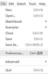
Open the Arduino IDE, click on the file in the top left corner, and select Preferences
-
Add the following link to the attached board manager URL, and then click OK
https://github.com/earlephilhower/arduino-pico/releases/download/4.0.2/package_rp2040_index.json
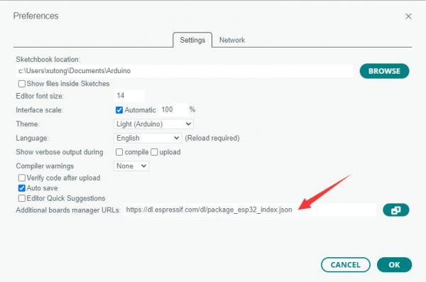
Note: If you already have an ESP32 board URL, you can use a comma to separate the URLs as follows:https://dl.espressif.com/dl/package_esp32_index.json,https://github.com/earlephilhower/arduino-pico/releases/download/4.0.2/package_rp2040_index.json
-
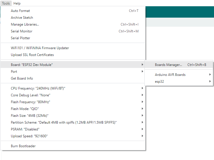
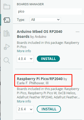
Click Tools > Development Board > Board Manager > Search pico, as my computer has already been installed, it shows that it is installed


Upload Demo at the First Time
-
Press and hold the BOOTSET button on the Pico board, connect the pico to the USB port of the computer via the Micro USB cable, and release the button after the computer recognizes a removable hard disk (RPI-RP2).
- Download the program and open D1-LED.ino under the arduino\PWM\D1-LED path
-
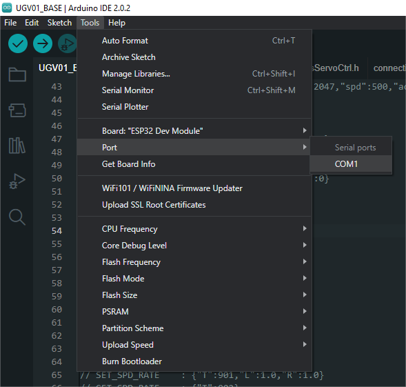
Click Tools --> Port, remember the existing COM, do not click this COM (the COM displayed is different on different computers, remember the COM on your own computer)
-
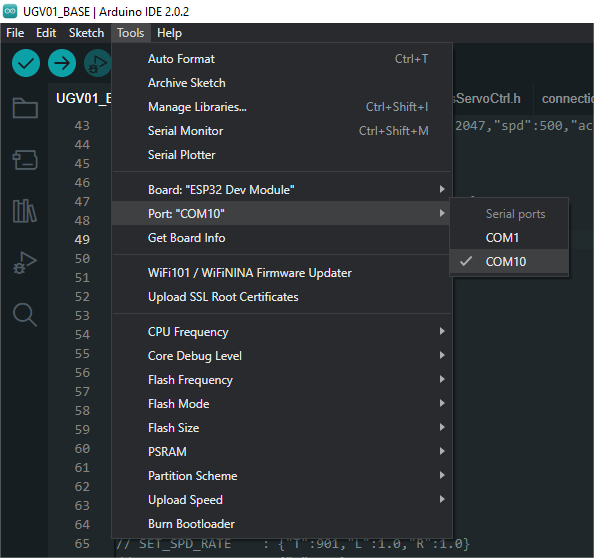
Connect the driver board to the computer using a USB cable. Then, go to Tools > Port. For the first connection, select uf2 Board. After uploading, when you connect again, an additional COM port will appear
-
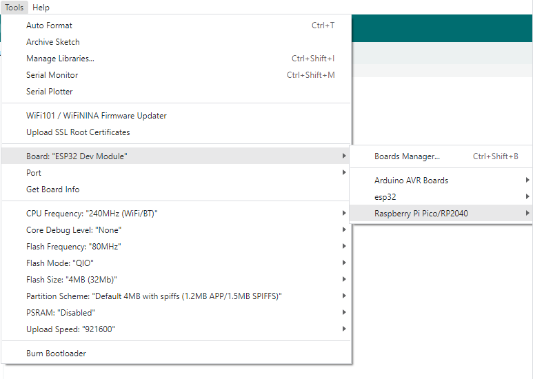
Click Tools > Development Board > Raspberry Pi Pico > Raspberry Pi Pico or Raspberry Pi Pico 2
- After setting it up, click the right arrow to upload the program


- If issues arise during this period, and if you need to reinstall or update the Arduino IDE version, it is necessary to uninstall the Arduino IDE completely. After uninstalling the software, you need to manually delete all contents within the C:\Users\[name]\AppData\Local\Arduino15 folder (you need to show hidden files to see this folder). Then, proceed with a fresh installation.
Open Source Demos
MircoPython video demo (github)
MicroPython firmware/Blink demos (C)
Raspberry Pi official C/C++ demo (github)
Raspberry Pi official micropython demo (github)
Arduino official C/C++ demo (github)
Support
Technical Support
If you need technical support or have any feedback/review, please click the Submit Now button to submit a ticket, Our support team will check and reply to you within 1 to 2 working days. Please be patient as we make every effort to help you to resolve the issue.
Working Time: 9 AM - 6 PM GMT+8 (Monday to Friday)