Pico Environment Sensor
| ||
Overview
The Pico-Environment-Sensor gives Raspberry Pi Pico the ability to collect environmental data like temperature & humidity, air pressure, ambient light intensity, VOC, UV rays, etc. It can also be used to build a robot that can detect motion and orientation.
Features
- Standard Raspberry Pi Pico header, supports Raspberry Pi Pico series.
- Onboard TSL25911FN digital ambient light sensor, for measuring IR and visible light.
- Onboard BME280 sensor, for measuring temperature, humidity, and air pressure.
- Onboard ICM20948 motion sensor, accelerometer, gyroscope, and magnetometer.
- Onboard LTR390-UV-1 sensor, for measuring UV rays.
- Onboard SGP40 sensor, for detecting ambient VOC.
- I2C bus allows retrieving data by just using two wires.
Specifications
| TSL25911FN DIGITAL AMBIENT LIGHT SENSOR | |
| I2C address | 0 x 29 |
| Effective range | 0~88000 Lux |
| BME280 TEMPERATURE, HUMIDITY, AND AIR PRESSURE SENSOR | |
| I2C address | 0 x 76 |
| Temperature detection | -40 ~ 85℃ (0.01℃ resolution, ±1℃ accuracy) |
| Humidity detection | 0~100%RH (0.008%RH resolution, ±3%RH accuracy, 1s response time, ≤2%RH delay) |
| Air presure detection | 300~1100hPa (0.18Pa resolution, ±1hPa accuracy) |
| ICM20948 MOTION SENSOR (9-DOF: 3-AXIS ACCELEROMETER, 3-AXIS GYROSCROPE, 3-AXIS MAGNETOMETER) | |
| I2C address | 0 x 68 |
| Accelerometer resolution | 16-bit |
| Accelerometer range (configurable) | 2, ±4, ±8, ±16g |
| Gyroscope resolution | 16-bit |
| Gyroscope range (configurable) | ±250, ±500, ±1000, ±2000°/sec |
| Magnetometer resolution | 16-bit |
| Magnetometer range | ±4900µT |
| LTR390-UV-1 UV SENSOR | |
| I2C address | 0 x 53 |
| Response wavelength | 280nm - 430nm |
| SGP40 VOC Sensor | |
| I2C address | 0 x 59 |
| Measuring range | 0 ~ 1,000 ppm ethanol equivalent |
| Limit condition | < 0.05 ppm ethanol equivalent OR < 10 % preset concentration point (the larger one should prevail) |
| Response time | < 10 s (tau 63 %) |
| Start time | < 60 s |
| On-chip humidity compensation support | |
How to Connect
As shown below: directly connect to the GPIO headers of the Jetson Nano.

Onboard Resource
- digital ambient light sensor, for measuring IR and visible light
2. LTR390-UV-1
- UV sensor
3. SGP40
- VOC sensor
4. ICM20948
- 3-axis accelerometer, 3-axis gyroscrope, 3-axis magnetometer
5. Voltage translator
- 5V to 3.3V/1.8V
6. BME280
- temperature, humidity, and air pressure sensor
7. Logic level translator
- 3.3V ~ 1.8V
8. I2C selection
Sensor
Ambient Light Sensor
The TSL2591 is an optical intensity digitizer based on IIC bus communication. The sensor combines a broadband photodiode (visible and IR light) and an IR-responsive photodiode on a single CMOS integrated circuit capable of providing near-light adaptive response over an effective 16-bit dynamic range (16-bit resolution). Two integral ADCs convert the photodiode current to a digital output representing the irradiance measured on each channel. This digital output can be fed to a microprocessor, which uses an empirical formula to derive an illuminance (ambient light level) in lux to approximate the human eye response.
The sensor address is 0X29.
The following points need to be noted when using this sensor:
- The default is turned on the interrupt, if you do not need to comment out the corresponding code;
- The default range of the demo is limited, if the light suddenly changes a lot, please increase the range;
- There is a difference with the light intensity reader on the market, those are added to the lens.
Temperature, Humidity, and Ari Pressure Sensor
BME280 is for temperature, humidity, and air pressure sensors with the characteristics of low power consumption, high accuracy, and stability. It is suitable for environmental monitoring, weather prediction, altitude monitoring, and Internet of Things application scenarios.
Sensor address: 0 x 76.
Measuring range:
Temperature range: 40~85°C (resolution is 0.01°C, error ±1°C).
Humidity range: 0~100%RH (resolution is 0.008%RH, error ±3% RH)
Pressure range: 300~1100 hPa (resolution is 0.18Pa, error ±1 hPa)
Note:
- The measuring range should not exceed the measuring range, or it may be inaccurate.
- The pressure measured is atmospheric pressure, which normally fluctuates around the standard atmospheric pressure (1.013x 10^5 = 1013hPa).
- The measured temperature may be biased to the temperature above the jetson nano. If possible, fans can be added to avoid this situation during use.
- The higher the air temperature is, the lower the air pressure is. Because the higher the air temperature is, the air near the ground will expand and rise due to heat, resulting in a decrease in air density and air pressure. Instead, the pressure rises.
- Atmospheric pressure decreases with altitude, but there is no proportional relationship. The higher the altitude, the slower the decrease.
- The relationship between atmospheric pressure and altitude is as follows: as altitude increases, atmospheric pressure decreases. Theoretically, within the range of 3000M, atmospheric pressure decreases by 1mmHg, or about 133Pa, for every 12M increase.
9-axis Sensor
MPU9250 is a multi-chip module with 9-axis motion tracking, 3-axis acceleration, 3-axis gyroscope, and 3-axis magnetometer, and a built-in digital motion processing engine to reduce complex fusion algorithm data and reduce the load on the processor.
Sensor address: 0x68
Parameters:
Accelerometer characteristics:
- Resolution: 16-bit
- Measurement range (Optional): ±2, ±4, ±8, ±16g
- Operating current: 450uA
Gyroscope characteristics:
- Resolution: 16 bit
- Measurement range (Optional): ±250, ±500, ±1000, ±2000°/sec
- Operating current: 3.2mA
Magnetometer characteristics:
- Resolution: 16 bit
- Measurement range: ±4900µT
- Operating current: 280uA
Note:
- Acceleration (LSB, convert to g)
- Gyroscope angle velocity (LSB, convert to °/second)
- Magnetic electronic compass angle (°)
UV Sensor
The LTR390-UV-01 is a multifunctional optical measurement module with a focus on measuring ultraviolet light. The sensor supports the measured ambient light intensity.
The sensor address is: 0X53
The use of this sensor requires attention to the following points.
- The principle of operation is actually a pair of diodes, one sensitive to normal light and one sensitive to ultraviolet light, and the result is obtained by the calculation of both.
- The value readout is the original ADC data, if you want to calibrate can refer to the manual formula and combine it with the actual light intensity value, UV for correction.
- The data can be set differently by gain, which needs to be set according to the actual application environment.
- The manual does not specify the detection range, the actual measurement in the sun has a better effect or the best effect with a UV pen in 50cm thought.
VOC Sensor
SGP40 Sensirion's new digital VOC (Volatile Organic Compounds) sensor, easily integrated into air handling devices and air quality monitors, features a temperature-controlled miniature heating plate and a humidity-compensated indoor air quality signal that provides a complete sensor system on a single chip.
The sensor address is: 0X59
The following points need to be noted when using this sensor.
- The default Python demo outputs the VOC-processed algorithm value.
- The sensor work needs to be stabilized within 1 minute, as the internal is slowly heating up.
- Can be fed back to the SGP40 by measuring the current temperature and humidity so that the accuracy of the output will be higher.
- The sensor measurement range of 0 to 1,000 ppm ethanol equivalent.
C
C/C++ Development Environment Installation
- Before using the demos and tutorials, you need to set up the development environment and learn the basic usage of the project:
Windows
- Click here to download the demo, unzip it and enter the folder of Pico-Environment-Sensor-code\c.
- After entering Pico-Environment-Sensor-code\c, you can open the project with vs code.
- Choose the Compiler.
- Start to compile.
- Finish.
- Copy the Pico_Environment_Sensor.uf2 in build to Pico, and then it can automatically run the demo.
In Raspberry Pi
- Open the Raspberry Pi and run:
sudo apt-get install p7zip-full
cd ~
sudo wget https://files.waveshare.com/upload/f/f8/Pico-Environment-Sensor-code.7z
7zr x Pico-Environment-Sensor-code.7z -r -o./Pico-Environment-Sensor-code
cd ~/Pico-Environment-Sensor-code
cd c/build/
Demo Use
- Please operate the following tutorial on Raspberry Pi, due to the multi-platform and portable nature of CMake, it can also be compiled successfully on a PC, but the operation is slightly different and requires your own judgment.
- To perform the compilation, make sure that in the c directory:
cd ~/Pico-Environment-Sensor-code/c/
Create and enter the build directory, and add the SDK: ../../pico-sdk is the directory of your SDK. There is a build in our sample application, just enter it directly.
cd build
export PICO_SDK_PATH=../../pico-sdk
(Note: Be sure to write the right path to your own SDK)
Execute cmake to automatically generate the Makefile file:
cmake ..
Execute make to generate the executable file, you may wait for a long time as it is the first time to be compiled.
make -j9
After compiling, the uf2 file will be generated. Press the button on the Pico board, Pico can connect to the USB port of the Raspberry Pi via a Micro USB cable, and then release the buttons. After connecting, Raspberry Pi will automatically identify a movable disk (RPI-RP2), and copy main.uf2 in the build file to the recognizable movable disk (RPI-RP2).
cp Pico_Environment_Sensor.uf2 /media/pi/RPI-RP2/
Python
Windows
- Download the demo.
- Press and hold the BOOTSET button on the Pico board, connect the Pico to the USB port of the computer via the Micro USB cable and release the button when the computer recognizes a removable disk (RPI-RP2).
- Copy the pico_micropython_20221125.uf2 file from the UF2 directory to the recognized removable disk (RPI-RP2).
- Open the Thonny IDE (note: use the latest version of Thonny, otherwise there is no support package for Pico, the current latest version for Windows is v3.3.3).
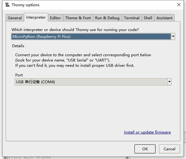
- Click Tools -> Settings -> Interpreter, and select Pico and the corresponding port as shown in the picture.
6. After connecting to Pico, save all the downloaded code to Pico, then run test.py, Thonny will print the sensor data as follows:
(1) Find the path of your downloaded program in the Thonny IDE.
(2) Upload all the Python to Pico.
(3) After uploading, open test.py for module testing.
(4) No save and the output value is normal, then the function is OK.
Raspberry Pi
- Demo download:
sudo apt-get install p7zip-full
cd ~
sudo wget  https://files.waveshare.com/upload/f/f8/Pico-Environment-Sensor-code.7z
7z x Pico-Environment-Sensor-code.7z -o./Pico-Environment-Sensor-code
cd ~/Pico-Environment-Sensor-code
1. The process of flashing the firmware is the same as on Windows, you can choose to copy the pico_micropython_20210121.uf2 file into pico on your PC or Raspberry Pi.
2. Open the Thonny IDE in Raspberry Pi Mountain (click Raspberry logo -> Programming -> Thonny Python IDE), you can check the version information in Help -> About Thonny.
To make sure your version has the Pico support package, also you can click on Tools -> Options... -> Interpreter to select MicroPico. -> Interpreter to select MicroPython (Raspberry Pi Pico and ttyACM0 port).
As shown in the image:

If your current Thonny version has no Pico support package, you should enter the following commands to update Thonny IDE:
sudo apt upgrade thonny
3. Click File -> Open... -> test.py, and run the script.
Resource
Documents
- Schematic
- BME280 Specification
- TSL25911 Specification
- ICM20948 Datasheet
- LTR-390UV Specification
- SGP40 Specification
Demo Codes
Development Softwares
- Zimo221.7z
- Image2Lcd.7z
- Font Library Tutorial
- Image Extraction Tutorial
- Thonny Python IDE (Windows V3.3.3)
Pico Getting Started
Firmware Download
Introduction
MicroPython Series
Install Thonny IDE
In order to facilitate the development of Pico/Pico2 boards using MicroPython on a computer, it is recommended to download the Thonny IDE
- Download Thonny IDE and follow the steps to install, the installation packages are all Windows versions, please refer to Thonny's official website for other versions
- After installation, the language and motherboard environment need to be configured for the first use. Since we are using Pico/Pico2, pay attention to selecting the Raspberry Pi option for the motherboard environment
- Configure MicroPython environment and choose Pico/Pico2 port
- Connect Pico/Pico2 to your computer first, and in the lower right corner of Thonny left-click on the configuration environment option --> select Configture interpreter
- In the pop-up window, select MicroPython (Raspberry Pi Pico), and choose the corresponding port
Flash Firmware
- Click OK to return to the Thonny main interface, download the corresponding firmware library and burn it to the device, and then click the Stop button to display the current environment in the Shell window
- Note: Flashing the Pico2 firmware provided by Micropython may cause the device to be unrecognized, please use the firmware below or in the package
- How to download the firmware library for Pico/Pico2 in windows: After holding down the BOOT button and connecting to the computer, release the BOOT button, a removable disk will appear on the computer, copy the firmware library into it
- How to download the firmware library for RP2040/RP2350 in windows: After connecting to the computer, press the BOOT key and the RESET key at the same time, release the RESET key first and then release the BOOT key, a removable disk will appear on the computer, copy the firmware library into it (you can also use the Pico/Pico2 method)
MicroPython Series
【MicroPython】 machine.Pin class function details
【MicroPython】machine.PWM class function details
【MicroPython】machine.ADC class function details
【MicroPython】machine.UART class function details
【MicroPython】machine.I2C class function details
【MicroPython】machine.SPI class function details
【MicroPython】rp2.StateMachine class function details
C/C++ Series
For C/C++, it is recommended to use Pico VS Code for development. This is a Microsoft Visual Studio Code extension designed to make it easier for you to create, develop, and debug projects for the Raspberry Pi Pico series development boards. No matter if you are a beginner or an experienced professional, this tool can assist you in developing Pico with confidence and ease. Here's how to install and use the extension.
- Official website tutorial: https://www.raspberrypi.com/news/pico-vscode-extension/
- This tutorial is suitable for Raspberry Pi Pico, Pico2 and the RP2040 and RP2350 series development boards developed by Waveshare
- The development environment defaults to Windows11. For other environments, please refer to the official tutorial for installation
Install VSCode
-
First, click to download pico-vscode package, unzip and open the package, double-click to install VSCode
Note: If vscode is installed, check if the version is v1.87.0 or later
Install Extension
-
Click Extensions and select Install from VSIX
-
Select the package with the vsix suffix and click Install
-
Then vscode will automatically install raspberry-pi-pico and its dependency extensions, you can click Refresh to check the installation progress
-
The text in the right lower corner shows that the installation is complete. Close VSCode
Configure Extension
-
Open directory C:\Users\username and copy the entire .pico-sdk to that directory
-
The copy is completed
-
Open vscode and configure the paths for the Raspberry Pi Pico extensions
The configuration is as follows:Cmake Path: ${HOME}/.pico-sdk/cmake/v3.28.6/bin/cmake.exe Git Path: ${HOME}/.pico-sdk/git/cmd/git.exe Ninja Path: ${HOME}/.pico-sdk/ninja/v1.12.1/ninja.exe Python3 Path: ${HOME}/.pico-sdk/python/3.12.1/python.exe
New Project
-
The configuration is complete, create a new project, enter the project name, select the path, and click Create to create the project
To test the official example, you can click on the Example next to the project name to select
-
The project is created successfully
-
Select the SDK version
-
Select Yes for advanced configuration
-
Choose the cross-compilation chain, 13.2.Rel1 is applicable for ARM cores, RISCV.13.3 is applicable for RISCV cores. You can select either based on your requirements
-
Select Default for CMake version (the path configured earlier)
-
Select Default for Ninjaversion
-
Select the development board
-
Click Complie to compile
-
The uf2 format file is successfully compiled
Import Project
- The Cmake file of the imported project cannot have Chinese (including comments), otherwise the import may fail
-
To import your own project, you need to add a line of code to the Cmake file to switch between pico and pico2 normally, otherwise even if pico2 is selected, the compiled firmware will still be suitable for pico
set(PICO_BOARD pico CACHE STRING "Board type")
Update Extension
-
The extension version in the offline package is 0.15.2, and you can also choose to update to the latest version after the installation is complete
Arduino IDE Series
Install Arduino IDE
-
First, go to Arduino official website to download the installation package of the Arduino IDE.

-
Here, you can select Just Download.

-
Once the download is complete, click Install.

Notice: During the installation process, it will prompt you to install the driver, just click Install
Arduino IDE Interface
-
After the first installation, when you open the Arduino IDE, it will be in English. You can switch to other languages in File --> Preferences, or continue using the English interface.

-
In the Language field, select the language you want to switch to, and click OK.

Install Arduino-Pico Core in the Arduino IDE
-
Open the Arduino IDE, click on the file in the top left corner, and select Preferences

-
Add the following link to the attached board manager URL, and then click OK
https://github.com/earlephilhower/arduino-pico/releases/download/4.0.2/package_rp2040_index.json
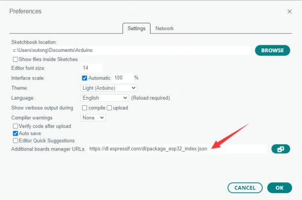
Note: If you already have an ESP32 board URL, you can use a comma to separate the URLs as follows:https://dl.espressif.com/dl/package_esp32_index.json,https://github.com/earlephilhower/arduino-pico/releases/download/4.0.2/package_rp2040_index.json
-
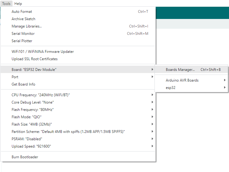
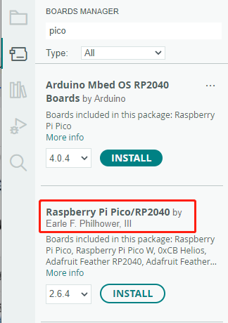
Click Tools > Development Board > Board Manager > Search pico, as my computer has already been installed, it shows that it is installed
Upload Demo at the First Time
-
Press and hold the BOOTSET button on the Pico board, connect the pico to the USB port of the computer via the Micro USB cable, and release the button after the computer recognizes a removable hard disk (RPI-RP2).
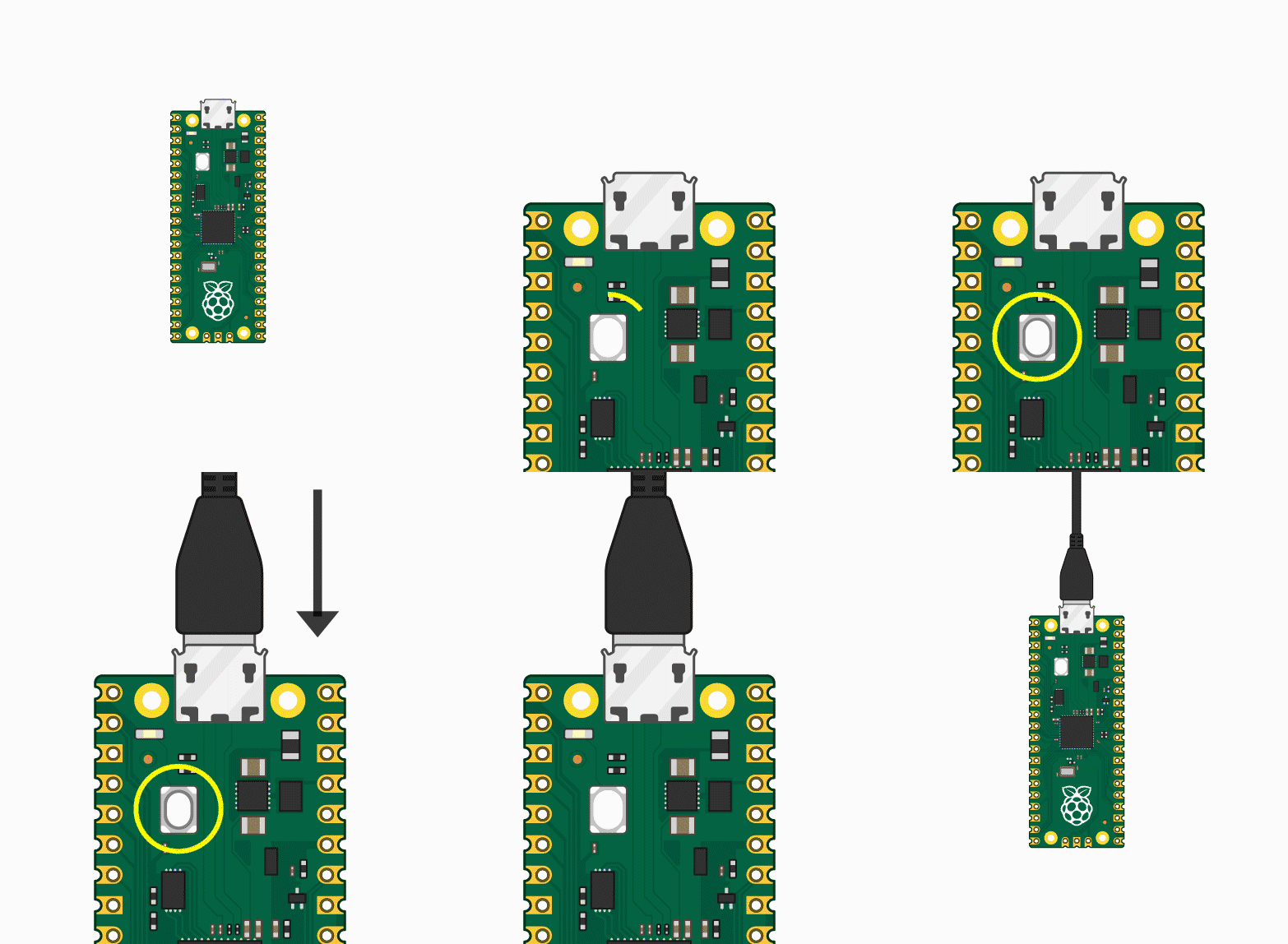
- Download the program and open D1-LED.ino under the arduino\PWM\D1-LED path
-
Click Tools --> Port, remember the existing COM, do not click this COM (the COM displayed is different on different computers, remember the COM on your own computer)
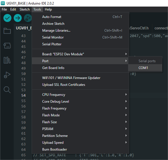
-
Connect the driver board to the computer using a USB cable. Then, go to Tools > Port. For the first connection, select uf2 Board. After uploading, when you connect again, an additional COM port will appear
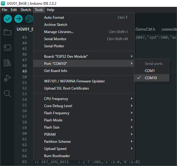
-
Click Tools > Development Board > Raspberry Pi Pico > Raspberry Pi Pico or Raspberry Pi Pico 2
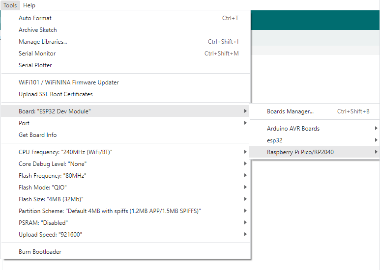
- After setting it up, click the right arrow to upload the program

- If issues arise during this period, and if you need to reinstall or update the Arduino IDE version, it is necessary to uninstall the Arduino IDE completely. After uninstalling the software, you need to manually delete all contents within the C:\Users\[name]\AppData\Local\Arduino15 folder (you need to show hidden files to see this folder). Then, proceed with a fresh installation.
Open Source Demos
MircoPython video demo (github)
MicroPython firmware/Blink demos (C)
Raspberry Pi official C/C++ demo (github)
Raspberry Pi official micropython demo (github)
Arduino official C/C++ demo (github)
Support
Technical Support
If you need technical support or have any feedback/review, please click the Submit Now button to submit a ticket, Our support team will check and reply to you within 1 to 2 working days. Please be patient as we make every effort to help you to resolve the issue.
Working Time: 9 AM - 6 PM GMT+8 (Monday to Friday)


