Raspberry-Pi-Pico-Basic-Kit
| ||
Overview
Introduction
Raspberry Pi Pico is a low-cost, high-performance microcontroller board with flexible digital interfaces. It incorporates Raspberry Pi's own RP2040 microcontroller chip, with a dual-core Arm Cortex M0+ processor running up to 133 MHz, embedded 264KB of SRAM, and 2MB of onboard Flash memory, as well as 26 x multi-function GPIO pins.
For software development, either Raspberry Pi's C/C++ SDK or the MicroPython is available. There are also complete development resources and tutorials to help you get started easily, and integrate it into end products quickly.
Features
- RP2040 microcontroller chip designed by Raspberry Pi in the United Kingdom.
- Dual-core Arm Cortex M0+ processor, the flexible clock running up to 133 MHz.
- 264KB of SRAM, and 2MB of onboard Flash memory.
- Castellated module allows soldering direct to carrier boards.
- USB 1.1 with device and host support.
- Low-power sleep and dormant modes.
- Drag-and-drop programming using mass storage over USB.
- 26 × multi-function GPIO pins.
- 2 × SPI, 2 × I2C, 2 × UART, 3 × 12-bit ADC, 16 × controllable PWM channels.
- Accurate clock and timer on-chip.
- Temperature sensor.
- Accelerated floating-point libraries on-chip.
- 8 × Programmable I/O (PIO) state machines for custom peripheral support.
Pinout
Dimension
Details of the Start Kit
- Raspberry Pi Pico with pre-soldered header x1
- Breadboard x1
- 1*3PIN yellow pin header x1
- USB-A to micro-B cable x1
- PIR sensor x2
- Breadboard wires x1
- Single-joint potentiometer x1
- 8-Bit WS2812 RGB LED x1
- Round button x3
- Alarm x1
- 330R resistor x10
- 5mm LED x6
- LCD1602 RGB Module x1
- Jumper wire female-female 10PIN x1
- Jumper wire male-female 10PIN x1
- Plastic storage box x1
Raspberry Pico
Raspberry Pi Pico is a low-cost, high-performance microcontroller board with flexible digital interfaces. It incorporates Raspberry Pi's own RP2040 microcontroller chip, with a dual-core Arm Cortex M0+ processor running up to 133 MHz, embedded 264KB of SRAM, and 2MB of onboard Flash memory, as well as 26x multi-function GPIO pins.
For software development, either Raspberry Pi's C/C++ SDK or the MicroPython is available. There are also complete development resources and tutorials to help you get started easily, and integrate it into end products quickly.
Features
- RP2040 microcontroller chip designed by Raspberry Pi in the United Kingdom.
- Dual-core Arm Cortex M0+ processor, the flexible clock running up to 133 MHz.
- 264KB of SRAM, and 2MB of onboard Flash memory.
- Castellated module allows soldering direct to carrier boards.
- USB 1.1 with device and host support.
- Low-power sleep and dormant modes.
- Drag-and-drop programming using mass storage over USB.
- 26 × multi-function GPIO pins.
- 2 × SPI, 2 × I2C, 2 × UART, 3 × 12-bit ADC, and 16 × controllable PWM channels.
- Accurate clock and timer on-chip.
- Temperature sensor.
- Accelerated floating-point libraries on-chip.
- 8 × Programmable I/O (PIO) state machines for custom peripheral support.
Pinout
LCD1602 RGB Module
Features
- Incorporates character LCD panel LCD1602.
- Adjustable RGB backlight color, up to 16M (2563) backlight colors in theory.
- Can display up to 16 X 2 characters, support screen scrolling, cursor movement, and other functions.
- Onboard AiP31068L LCD driver chip, PCA9633 RGB control chip.
- I2C control interface, only two signal pins are required, saving the IO resource.
- Compatible with 3.3V/5V operating voltage.
- Comes with online development resources and manual (Raspberry Pi/Jetson Nano/Arduino examples).
Specification
- Operating voltage: 3.3V/5V
- Interface: I2C
- LCD type: character LCD
- Controller: AiP31068L PCA9633DP2
- Display 64.5 x 16.0 mm
- Dimension: 87.0 × 32.0 × 13.0mm
- Operating current: 26mA (5V), 13mA (3.3V)
Pinout
| PIN | Description |
| VCC | 3.3V/5V |
| GND | GND |
| SDA | I2C data line |
| SCL | I2C clock line |
Working Protocol
Software Setup
Please follow the guides of Raspberry Pi to install and set up Pico for the Pico.
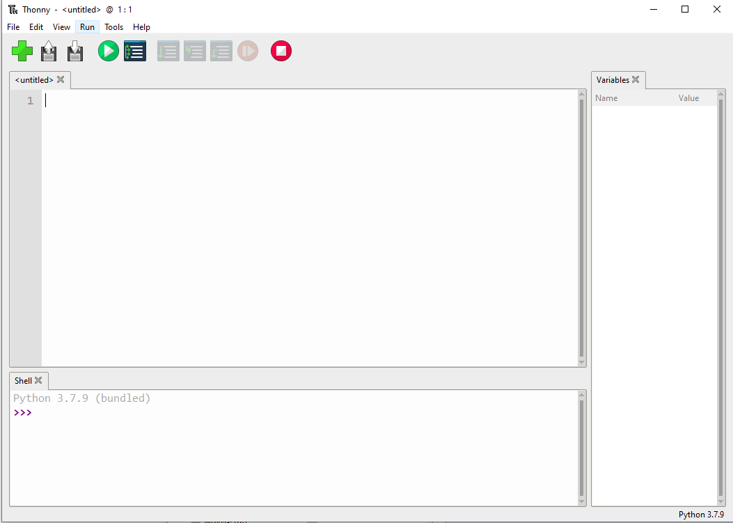
For easy use, we recommend you use the Thonny tool.
- Thonny website
- Please set the Thonny development environment to be RaspberryPi when setting.
- Configure the Micrpython environment and select the Pico port.
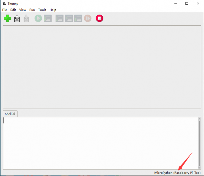
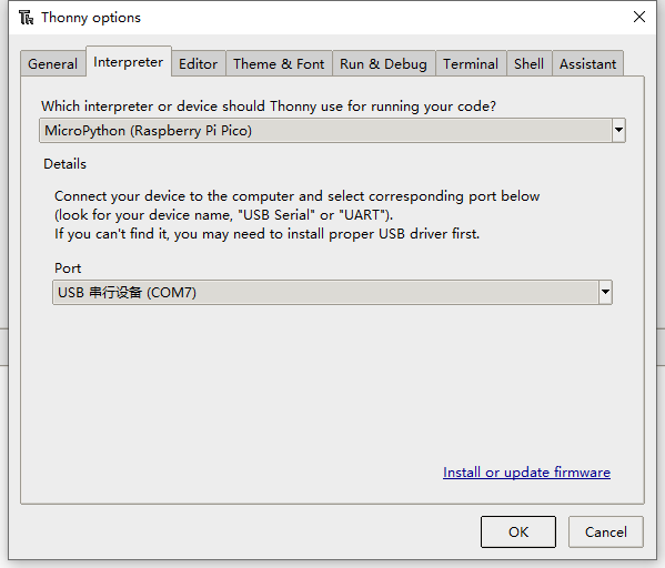
- First, connect the Raspberry Pi Pico to your computer, left click on the Configure environment option in the lower right corner of the Thonny --> Select Configure interpreter.
- In the pop-up window, select MicroPython (Raspberry Pi Pico), and select the corresponding port.
- Click OK and then back to Thonny, download the firmware library to the Pico. Then click Stop, and you can see the current environment in the Shell window.
- How to download the firmware library for Pico in Windows: Press and hold the BOOT key and connect to the computer, then release the BOOT key, a removable disk will appear on the computer, and copy the firmware library into it.
- How to download firmware library for RP2040 in Windows: After connecting to the computer, press the BOOT key and RESET key at the same time, release the RESET key, and then release the BOOT key, a removable disk will appear on the computer.
Copy the firmware library into it (you can also use the Pico method).
Examples
- Download Demo Codes to your Raspberry Pi and test.
External LED Example
Connect the boards as in the picture below. Connect the Pico to Raspberry Pi or PC. Open the Lesson-5 External LED example with Thonny. Run the example, and you will find that the red LED is flashing.

- Codes:
led_external = machine.Pin(15, machine.Pin.OUT) #Set GP15 to output Mode
while True:
   led_external.toggle() #Toggle the LED every 5 seconds.
   utime.sleep(5)
Traffic Light System Examples
Connect the boards as in the picture below. Connect the Pico to Raspberry Pi or PC. Open the Lesson-9 Traffic-Light-System example by Thonny, run the codes and test the traffic light, the buzzer sounds when you press the button.

- Codes
def button_reader_thread():  #Check if the button is pressed
   global button_pressed
   while True:
       if button.value() == 1:
           button_pressed = True

_thread.start_new_thread(button_reader_thread, ()) #Start a new thread to monitor the stats of button
while True:
   if button_pressed == True: #If the button is pressed, turn on the LED and let the buzzer work.
       led_red.value(1)
       for i in range(10):
           buzzer.value(1)
           utime.sleep(0.2)
           buzzer.value(0)
           utime.sleep(0.2)
       global button_pressed
       button_pressed = False
   led_red.value(1)
   utime.sleep(5)
   led_amber.value(1)
   utime.sleep(2)
   led_red.value(0)
   led_amber.value(0)
   led_green.value(1)
   utime.sleep(5)
   led_green.value(0)
   led_amber.value(1)
   utime.sleep(5)
   led_amber.value(0)
Burglar Alarm LED Buzzer Examples
Connect the boards as in the picture below. Connect the Pico to Raspberry Pi or PC. Open the Lesson-14 Burglar Alarm LED Buzzer examples by Thonny. The LED lights on if an object is moving around the Passive infrared sensor and the buzzer will indicate.

- Codes
def pir_handler(pin):  #Interrupt process function
   print("ALARM! Motion detected!")
   for i in range(50):
       led.toggle()
       buzzer.toggle()
       utime.sleep_ms(100)
sensor_pir.irq(trigger=machine.Pin.IRQ_RISING, handler=pir_handler)#Enable the Interrupt, the interrupt function is called when motions is detected.
while True:  #Toggle LED every 5s
   led.toggle()
   utime.sleep(5)
Potentiometer Example
Connect the boards as in the picture below. Connect the Pico to Raspberry Pi or PC. Open the Lesson-16 Potentiometer example by Thonny, you can adjust the potentiometer and check if the voltage printed to the Sheel window are changing as well.

- Codes
potentiometer = machine.ADC(26) #Set the GP26 pin as analog input
conversion_factor = 3.3 / (65535)
while True:
   voltage = potentiometer.read_u16() * conversion_factor #Convert the sampled data to voltage value
   print(voltage) #Print the voltage data, it chanaged according to the sliding rheostat.
   utime.sleep(2)
WS2812 Example
Connect the boards as in the picture below. Connect the Pico to Raspberry Pi or PC. Open the WS2812_RGB_LED.py file of Lesson-25 WS2812 example by Thonny, the LEDs light in Blue, Red, Green, and White.

- Code
#This code uses the state machine mechanism. The following code is a decorator where we can initialize the hardware, set the pin level, etc.
#label("bitloop") We can define some tags in our code so that we can jump to them.
#jmp(not_x,"do_zero") If x=0, we jumpt to do_zero.
#nop() .set(0) [T2 - 1] The code jumpt to here if x = 0.
@asm_pio(sideset_init=PIO.OUT_LOW, out_shiftdir=PIO.SHIFT_LEFT, autopull=True, pull_thresh=24)
def ws2812():
   T1 = 2
   T2 = 5
   T3 = 1
   label("bitloop")
   out(x, 1)               .side(0)    [T3 - 1]
   jmp(not_x, "do_zero")   .side(1)    [T1 - 1]
   jmp("bitloop")          .side(1)    [T2 - 1]
   label("do_zero")
   nop()                   .side(0)    [T2 - 1]
# Create the StateMachine with the ws2812 program, outputting on Pin(22).
sm = StateMachine(0, ws2812, freq=8000000, sideset_base=Pin(0)) #Create the stats machine
# Start the StateMachine, it will wait for data on its FIFO.
sm.active(1) #Start the stats machine
# Display a pattern on the LEDs via an array of LED RGB values.
ar = array.array("I", [0 for _ in range(NUM_LEDS)])
print(ar)
print("blue")
for j in range(0, 255):
   for i in range(NUM_LEDS):
       ar[i] = j
   sm.put(ar,8)  #put() is put the data to output FIFO of the stats machine
   time.sleep_ms(5)
LCD1602 I2C Example
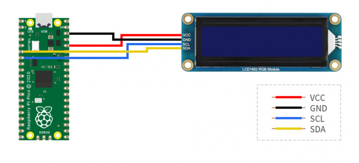
Connect the boards as in the picture below. Connect the Pico to Raspberry Pi or PC. Open the Lesson-21 LCD1602 I2C example by Thonny, you need to first save the RGB1602.py to Pico and then run the Choose_Color.py file. The LCD will change color every 5s. If you run the Discoloratio.py file, the LED displays RGB colors.

- Codes
Choose_Color.py
#Define colors
rgb9 = (0,255,0) #green
lcd.setCursor(0, 0) #Set the position of cursor
# print the number of seconds since reset:
lcd.printout("Waveshare") #Print the string
lcd.setCursor(0, 1) #Move the cursor to second row.
lcd.printout("Hello,World!")#Print the string
lcd.setRGB(rgb1[0],rgb1[1],rgb1[2]); #Set the back light
Discoloration.py
t=0
while True:

   r = int((abs(math.sin(3.14*t/180)))*255);  #RGB changes as time goes
   g = int((abs(math.sin(3.14*(t+60)/180)))*255);
   b = int((abs(math.sin(3.14*(t+120)/180)))*255);
   t = t + 3;
   lcd.setRGB(r,g,b);#Set the RGB data again.
# set the cursor to column 0, line 1
   lcd.setCursor(0, 0) #Set the curson to the first row.
# print the number of seconds since reset:
   lcd.printout("Waveshare")#Print the string
   lcd.setCursor(0, 1) #Set the cursor to second row
   lcd.printout("Hello,World!")#Print the string
   time.sleep(0.3)
Resources
Supporting Resources
Documents
Demo
Application
Official Resources
Raspberry Pi Official Documents
- Get Started with MicroPython on Raspberry Pi Pico
- Raspberry Pi related books download
- Raspberry Pi Pico Schematic
- Pico Pinout definition
- Getting started with Pico
- Pico C SDK User Manual
- Pico Python SDK User Manual
- Pico Datasheet
- RP2040 Datasheet
- RP2040 Hardware Design Manual
Raspberry Pi Open Source Demos
Other Documents
Pico W
Firmware
Pico
User Manual
Demo Codes
Support
Technical Support
If you need technical support or have any feedback/review, please click the Submit Now button to submit a ticket, Our support team will check and reply to you within 1 to 2 working days. Please be patient as we make every effort to help you to resolve the issue.
Working Time: 9 AM - 6 PM GMT+8 (Monday to Friday)


