Tutorial IV: Motor Without Encoder Control Demo
Modules Usage Tutorial
- How To Install Arduino IDE
- Tutorial I: Motor With Encoder Control Demo
- Tutorial II: Motor With Encoder Control Demo 2
- Tutorial III: Motor With Encoder Control Demo 3
- Tutorial IV: Motor Without Encoder Control Demo
- Tutorial V: ST3215 Serial Bus Servo Control Demo
- Tutorial VI: PWM Servo Control Demo
- Tutorial VII: IMU Data Reading Demo
- Tutorial VIII: SD Card Reading Demo
- Tutorial IX: INA219 Voltage And Current Monitoring Demo
- Tutorial X: OLED Screen Control Demo
- Tutorial XI Lidar and Publishing Lidar Topics in ROS2
- General Driver for Robots WIKI Main Page
Motor Without Encoder
As the motor without an encoder can not get the speed feedback, it only supports open-loop control. The motor without encoder control demo is provided as follows.
Demo
Upload Demo
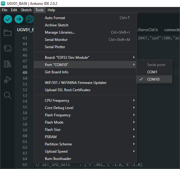
After downloading the zip file, double-click it to open nospeedget.ino, connect the multifunctional driver board to the computer with a USB cable (here the Type-C port of the USB of the multifunctional driver board is inserted), click "Tools" -> "Ports", and then click the newly appeared COM port.

In Arduino IDE, click "Tools" → "Development Board" → "ESP32" → "ESP32 Dev Module". Upload the demo after selecting the board and the port. After uploading the demo, connect the encoderless motor to the motor interface PH2.0 2P on the driver board, connect the XH2.54 power supply interface to the power supply, and run the demo, and you can see the motor start to rotate.
Demo Analysis
//The following defines the ESP32 pin of the TB6612 control
//Motor A
const uint16_t PWMA = 25;
const uint16_t AIN2 = 17;
const uint16_t AIN1 = 21;

//Motor B
const uint16_t BIN1 = 22;
const uint16_t BIN2 = 23;
const uint16_t PWMB = 26;

//Define the precision of the PWM, with a precision of 8, the PWM value is in the range of 0-255 (2^8-1)
const uint16_t ANALOG_WRITE_BITS = 8;

//PWM frequency of pins used for PWM outputs
int freq = 100000;

//Defines PWM channel
int channel_A = 0;
int channel_B = 1;
int resolution = ANALOG_WRITE_BITS;

void initMotors(){
  //Setting the operating mode of the ESP32 pin used to control the TB6612FNG
  pinMode(AIN1, OUTPUT);
  pinMode(AIN2, OUTPUT);
  pinMode(PWMA, OUTPUT);
  pinMode(BIN1, OUTPUT);
  pinMode(BIN2, OUTPUT);
  pinMode(PWMB, OUTPUT);

  //Set the channel, frequency, and precision of the ESP32 pin used to control the PWM outputs
  ledcSetup(channel_A, freq, resolution);
  //Bind PWMA pin to A-channel
  ledcAttachPin(PWMA, channel_A);

  ledcSetup(channel_B, freq, resolution);
  ledcAttachPin(PWMB, channel_B);

}

void forwardA(uint16_t pwm){
  //Setting the direction of rotation of the A motor
  digitalWrite(AIN1, LOW);
  digitalWrite(AIN2, HIGH);
  //Setting the PWM output duty cycle of channel A
  ledcWrite(channel_A, pwm);
}

void forwardB(uint16_t pwm){
  digitalWrite(BIN1, LOW);
  digitalWrite(BIN2, HIGH);
  ledcWrite(channel_B, pwm);
}

void setup() {
  //Initialize the motor pin and PWM setting
  initMotors();
}

void loop() {
  //Call forward function
  forwardA(400);
  forwardB(400);
}