E-Paper Driver HAT
| ||
Introduction
Version Description
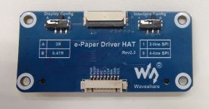
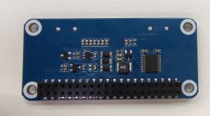
Rev2.3
- Pictures:
- Different versions:
- RST pin now is for reset control, and not for power on/off.
- Add a new PWR pin for power on/off.
- Smaller and thinner package for the inductor.
- PH2.0 8Pin connector is replaced with GH1.25 9Pin connector.
- The version silk print is updated with Rev2.3.
- If you want to upgrade to this version, you can choose one of the following ways:
- Update the program to the newest one (Arduino program only supports 7.5inch e-Paper, 7.5inch e-Paper (B), 5.83inch e-Paper, 5.83inch e-Paper (B), 2.9inch e-Paper (D), 2.13inch e-Paper (D)).
- Connect PWR pin to 3.3V.
- The empty pad on the back side is soldered with a 47K (or similar) resistor.
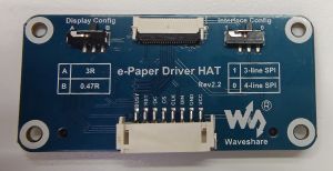
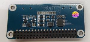
Rev2.2
- Pictures:
Features
- Based on the Raspberry Pi 40pin GPIO header, supports Raspberry Pi series boards and Jetson Nano.
- Leading SPI control interface for connecting Raspberry Pi, Arduino, Nucleo, etc.
- The onboard voltage converter, compatible with 3.3V/5V MCUs
- Provide online resources and manuals (including Raspberry/Jetson Nano/Arduino/STM32 demos).
Parameter
- Operating voltage: 3.3V/5V (Please make sure the power supply is consistent with the logic voltage, otherwise it can not be operated normally.)
- Communication interface: 3-wire SPI, 4-wire SPI
- Outline dimension: 65mm x 30.2mm
- Mounting hole size: 3.0mm
Display Config
| Resistor (Display Config) | Display |
| 0.47R (B) | 2.13inch e-Paper (D), 2.7inch e-Paper, 2.9inch e-Paper (D) |
| 4.01inch e-Paper (F), 4.2inch e-Paper (C), 5.65inch e-Paper (F) | |
| 5.83inch e-Paper, 5.83inch e-Paper (B), 7.5inch e-Paper | |
| 7.5inch e-Paper (B) | |
| 3R (A) | 1.54inch e-Paper, 1.54inch e-Paper(B), 2.13inch e-Paper |
| 2.13inch e-Paper (B), 2.66inch e-Paper, 2.66inch e-Paper (B) | |
| 2.9inch e-Paper, 2.9inch e-Paper (B),3.7inch e-Paper | |
| 4.2inch e-Paper, 4.2inch e-Paper (B), 13.3inch e-Paper (B) | |
| 13.3inch e-Paper |
- It mainly affects the display effect. If you find that the display is abnormal, you can turn the switch to the other end.
Hardware Connection
Raspberry Pi
When connecting to the Raspberry Pi, you can directly plug the board into the 40PIN header of the Raspberry Pi, and be careful to match the pins.
If you choose to connect the board with an 9PIN cable, please refer to the table below:
| e-Paper | Raspberry Pi | |
| BCM2835 | Board | |
| VCC | 3.3V | 3.3V |
| GND | GND | GND |
| DIN | MOSI | 19 |
| CLK | SCLK | 23 |
| CS | CE0 | 24 |
| DC | 25 | 22 |
| RST | 17 | 11 |
| BUSY | 24 | 18 |
| PWR | 18 | 12 |
Jetson Nano
The 40PIN header of the Jetson Nano is compatible with the 40pin GPIO header on the Raspberry Pi, and a Jetson.GPIO library with an API that is identical to the RPI.GPIO library of the Raspberry Pi is provided. Therefore, the pin number used here is the same as on the Raspberry Pi. When using the 40PIN header, you can directly plug the module into the Jetson Nano's 40-pin header.
If you choose to connect the board with 9PIN cable, please refer to the table below:
| e-Paper | Jetson Nano Developer Kit | |
| BCM2835 | Board | |
| VCC | 3.3V | 3.3V |
| GND | GND | GND |
| DIN | 10 (SPI0_MOSI) | 19 |
| CLK | 11 (SPI0_SCK) | 23 |
| CS | 8 (SPI0_CS0) | 24 |
| DC | 25 | 22 |
| RST | 17 | 11 |
| BUSY | 24 | 18 |
| PWR | 18 | 12 |
Sunrise X3 Pi
When connecting to the Sunrise X3 Pi, you can directly plug the board into the Sunrise X3 Pi's 40-pin header. Please make sure to align the pins correctly for a secure connection.
If you choose to connect with 9PIN cable, please refer to the pinout table below:
| e-Paper | Sunrise X3 Pi | |
| BCM | Board | |
| VCC | 3.3V | 3.3V |
| GND | GND | GND |
| DIN | MOSI | 19 |
| CLK | SCLK | 23 |
| CS | CE0 | 24 |
| DC | 25 | 22 |
| RST | 17 | 11 |
| BUSY | 24 | 18 |
| PWR | 18 | 12 |
STM32
To connect with 9PIN cable, please refer to the pinout table below:
| e-Paper | STM32 |
| VCC | 3.3V |
| GND | GND |
| DIN | PA7 |
| CLK | PA5 |
| CS | PA4 |
| DC | PA2 |
| RST | PA1 |
| BUSY | PA3 |
| PWR | PA6 |
Arduino
To connect with 9PIN cable, please refer to the pinout table below:
| e-Paper | Arduino UNO | Mega2560 |
| VCC | 5V | 5V |
| GND | GND | GND |
| DIN | D11 | D51 |
| CLK | D13 | D52 |
| CS | D10 | D10 |
| DC | D9 | D9 |
| RST | D8 | D8 |
| BUSY | D7 | D7 |
| BUSY | D6 | D6 |
Resources
Documentation
Related E-Paper Wiki
- 1.54inch e-Paper Module
- 1.54inch e-Paper Module (B)
- 1.54inch e-Paper Module (C)
- 1.64inch e-Paper Module (G)
- 2.13inch e-Paper HAT
- 2.13inch e-Paper HAT (B)
- 2.13inch e-Paper HAT (C)
- 2.13inch e-Paper HAT (D)
- 2.66inch e-Paper Module
- 2.66inch e-Paper Module (B)
- 2.7inch e-Paper HAT
- 2.7inch e-Paper HAT (B)
- 2.9inch e-Paper Module
- 2.9inch e-Paper Module (B)
- 2.9inch e-Paper Module (C)
- 2.9inch e-Paper HAT (D)
- 3inch e-Paper Module (G)
- 3.52inch e-Paper HAT
- 3.7inch e-Paper HAT
- 4.01inch e-Paper HAT (F)
- 4.2inch e-Paper Module
- 4.2inch e-Paper Module (B)
- 4.2inch e-Paper Module (C)
- 5.65inch e-Paper Module (F)
- 5.83inch e-Paper HAT
- 5.83inch e-Paper HAT (B)
- 5.83inch e-Paper HAT (C)
- 7.3inch e-Paper HAT (G)
- 7.5inch e-Paper HAT
- 7.5inch e-Paper HAT (B)
- 7.5inch e-Paper HAT (C)
- 7.5inch HD e-Paper HAT
- 7.5inch HD e-Paper HAT (B)
- 13.3inch e-Paper HAT (K)
Related Resources
- Waveshare e-Paper display with SPI
- Pisugar case
- For Meage2560, you can refer to this guide
- Raspberry Pi Documentation
Development Resources
- E-Paper Floyd-Steinberg
- Image2Lcd.7z
- Image2Lcd Image Modulo
- Zimo221.7z
- Ink Screen Font Library Tutorial
- E-Paper_API_Analysis
FAQ
Questions about Software
- Enter the command: ls /dev/spi*.
- The result may appear as shown in the figure.
- This is because the SPI interface is occupied in the /boot/config.txt file.
{{{5}}}
- Our demo uses STM32f103ZET6. If the customer modifies other models in MDK, such as STM32F103RBT6, the RAM space becomes smaller, and the stack size and heap size in the startup file need to be modified on the original basis.
{{{5}}}
- When transmitting B/W data, use Data Start Transmission 1; When transmitting RED data, use Data Start Transmission 2.
{{{5}}}
- The border display color can be set through the Border Waveform Control register or the VCOM AND DATA INTERVAL SETTING register.
{{{5}}}
- In this case, the customer needs to reduce the position of the partial refresh and clear the screen after 5 rounds of partial refreshing (increasing the voltage of VCOM can improve the color, but it will increase the afterimage).
{{{5}}}
- The process of re-awakening the e-Paper screen is actually the process of re-powering. Therefore, when the EPD wakes up, the screen must be cleared first, so as to avoid the afterimage phenomenon to the greatest extent.
{{{5}}}
- It may be caused by the unsuccessful SPI driver.
- 1. First check whether the wiring is correct.
- 2. Check whether the SPI is enabled and whether the parameters are configured correctly (SPI baud rate, SPI mode and other parameters).
- 1. First check whether the wiring is correct.
{{{5}}}
- The full refresh initialization function needs to be added when the e-Paper screen is switched from partial refresh to full refresh.
{{{5}}}
- It may be a demo based on the BCM2835 library that has run the C language before. At this time, you need to restart the Raspberry Pi and then run the Python demo.
{{{5}}}
- Install the imaging library using the command "sudo apt-get install python-imaging".
{{{5}}}
Questions about Hardware
- Yes, now there is a level conversion chip onboard, supporting a 5V drive.
{{{5}}}
- The rated input voltage of the e-Paper screen is 2.3~3.6V. If it is a 5V system, level conversion is required. In addition, the voltage should not be lower than 2.5V, so as not to affect the display effect of the e-Paper screen.
- Device selection can use the model in the schematic diagram we provide or choose according to the datasheet.
{{{5}}}
- Yes, pay attention to the correct timing.
{{{5}}}
- Check if SPI communication is normal.
- Confirm whether the BUSY pin is normally initialized to input mode.
- It may be that there is no normal reset, try to shorten the duration of the low level during reset (because the power-off switch is added to the drive circuit, the reset low level is too long, which will cause the drive board to power off and cause the reset to fail).
- If the busy function sends the 0x71 command, you can try to comment it out.
{{{5}}}
- 1.64inch, 2.36inch, 3inch, 0.5mm pitch, 26Pin.
- 1.02inch, 0.5mm pitch, 30Pin.
- 4.37inch, 7.3inch, 0.5mm pitch, 50Pin.
- The rest (non-parallel ports) are 0.5mm pitch, 24Pin.
{{{5}}}
- Cable socket 0.5-XXpin rear-flip 2.0H (FPC connector).
{{{5}}}
Questions about Screen
- 【Working conditions】Temperature range: 0~40°C (seven-color screen: 15~35°C); Humidity range: 35%~65%RH.
- 【Storage conditions】Temperature range: below 30°C; Humidity range: below 55%RH; Maximum storage time: 6 months.
- 【Transportation conditions】Temperature range: -25~50°C; Maximum transportation time: 10 days.
- 【After unpacking】Temperature range: 20°C±5°C; Humidity range: 50±5%RH; Maximum storage time: Assemble within 72 hours.
{{{5}}}
- Refresh mode
- Full refresh: The e-Paper screen will flicker several times during the refresh process (the number of flickers depends on the refresh time), and the flicker is to remove the afterimage to achieve the best display effect.
- Partial refresh: The e-Paper screen has no flickering effect during the refresh process. Users who use the partial refreshing function note that after refreshing several times, a full refresh operation should be performed to remove the residual image, otherwise the residual image problem will become more and more serious, or even damage the screen (currently only some black and white e-Paper screens support partial refreshing, please refer to product page description).
- Full refresh: The e-Paper screen will flicker several times during the refresh process (the number of flickers depends on the refresh time), and the flicker is to remove the afterimage to achieve the best display effect.
- Refresh rate
- During use, it is recommended that customers set the refresh interval of the e-Paper screen to at least 180 seconds (except for products that support the partial refresh function).
- During the standby process (that is, after the refresh operation), it is recommended that the customer set the e-Paper screen to sleep mode, or power off (the power supply part of the e-Paper screen can be disconnected with an analog switch) to reduce power consumption and prolong the life of the e-Paper screen. (If some e-Paper screens are powered on for a long time, the screen will be damaged beyond repair.)
- During the use of the three-color e-Paper screen, it is recommended that customers update the display screen at least once every 24 hours (if the screen remains the same screen for a long time, there will be a screen burn that is difficult to repair).
- During use, it is recommended that customers set the refresh interval of the e-Paper screen to at least 180 seconds (except for products that support the partial refresh function).
- Usage Environment
- The e-Paper displays are recommended for indoor use and not for outdoor use.
- If the usage scenario is outdoors, we do not guarantee the display effect. If the e-Paper screen is damaged due to outdoor use, we do not provide warranty service.
- Here are some protective measures for outdoor use, but we do not guarantee that the e-Paper screen will function normally even after taking these precautions:
- Avoid exposing the e-Paper screen to direct sunlight and ensure UV protection. Prolonged exposure to strong light can dry out the charged particles, rendering them inactive and unable to refresh, which is irreversible.
- Completely cover the white glue part of the e-Paper screen's connection ribbon with 3M tape. Complete coverage and no coverage show different effects under UV light.
- Place the e-Paper screen in relatively shaded areas, such as under trees or the shadow of eaves.
- When designing e-Paper screen products, customers should ensure that the usage environment meets the requirements of the e-Paper screen.
{{{5}}}
- Ideally, with normal use, it can be refreshed 1,000,000 times (1 million times).
{{{5}}}
- Power on the development board for a long time, after each refresh operation, it is recommended to set the screen to sleep mode or directly power off, otherwise, the screen may burn out when the screen is in a high voltage state for a long time.
{{{5}}}
- Yes, but you need to re-initialize the electronic paper with software.
{{{5}}}
- Maybe the SPI rate is too high, resulting in data loss, try to reduce the SPI rate.
- Insufficient or unstable power supply leads to data loss.
- The data cable is so long to cause data loss, the extension cable should not exceed 20cm.
{{{5}}}
- The display gray scale of electrophoretic electronic paper is determined by the spatial position of the particles in the Microcapsule or Microcup. The electrophoresis phenomenon occurs between black particles and white particles under the action of voltage. This voltage sequence that promotes the electrophoretic movement of the particles is the driving waveform of the electronic paper. The driving waveform is the core part of the electronic paper display, and the optimization of the driving waveform will directly affect the display effect of the display. The driving waveform file is used to describe the parameters formed by the voltage sequence that promotes the electrophoretic movement of the particles, and it needs to be called regularly when the electronic paper is refreshed.
- For different batches of e-Paper diaphragms, electrophoretic matrices require different voltage values when driving the display due to materials, manufacturing processes, etc. The waveform of the e-Paper screen is reflected in the relationship between grayscale, voltage and temperature. Generally speaking, after each batch of electrophoresis matrix is generated, there will be a corresponding waveform file in the form of a .wbf file. The film manufacturer will provide the waveform file and electrophoresis matrix to the manufacturer of the e-Paper screen, and then the manufacturer of the e-Paper screen integrates the protection board, substrate and driver and then provides it to customers; if the waveform file does not correspond to the screen, it is likely that the display cannot be displayed or the display effect is unsatisfactory. Generally, the waveform file has OTP built into the driver IC of the e-Paper screen when leaving the factory, and some programs we provide also called external waveform files to drive the e-Paper screen.
{{{5}}}
- LUT is the abbreviation of LOOK UP TABLE, and OTP is the abbreviation of ONE TIME PROGRAM. The original intention of LUT is to load waveform files, and the waveform files are divided into OTP and REGISTER. Among them, OTP is the built-in waveform storage method, and REGISTER is the external waveform storage method.
{{{5}}}
- There are mainly two types of e-Paper screens.
- One is to refresh the background image first.
- The other is to alternately refresh old data and new data.
- One is to refresh the background image first.
{{{5}}}
- Simultaneous partial refreshing in different locations needs to be operated in the program design, that is, first refreshing the data of different locations into the electronic paper IC, and finally doing the Update/TurnOnDisplay uniformly.
{{{5}}}
- Yes, when the e-Paper is batched, there will be some color difference, which is a normal phenomenon. Store the e-Paper faces up to reduce the reddish/yellowishness to a certain extent.
{{{5}}}
- With film.
{{{5}}}
- At present, all screens have built-in temperature sensors, and you can also use IIC pins external LM75 temperature sensor.
{{{5}}}
Support
Technical Support
If you need technical support or have any feedback/review, please click the Submit Now button to submit a ticket, Our support team will check and reply to you within 1 to 2 working days. Please be patient as we make every effort to help you to resolve the issue.
Working Time: 9 AM - 6 PM GMT+8 (Monday to Friday)


