Details
360° High Torque Programmable Magnetic Encoder

| PRODUCT TYPE | ST3215 serial bus servo |
|---|---|
| TORQUE | 30kg.cm@12V |
| ROTATION ANGLE | 360° (0~4095) |
| POSITION SENSOR RESOLUTION | 360° / 4096 |
| MECHANISM LIMITED ANGLE | No Limit |
| OPERATING VOLTAGE | 6 ~ 12.6 V |
| GEAR | high precision metal gear |
| NO-LOAD SPEED | 0.222sec / 60° (45RPM)@12V |
| Encoder TYPE | 360° Magnetic Encoder |
| ID RANGE | 0 ~ 253 |
| BAUDRATE | 38400bps ~ 1Mbps (1Mbps by default) |
| FEEDBACK | Position, Load, Speed, Input Voltage |
| NO-LOAD CURRENT | 180 mA |
| LOCKED-ROTOR CURRENT | 2.7A |
| kt | 11kg.cm/A |
- Servos will provide various feedback like position, speed, torque lock, operating mode (servo mode, servo motor mode, etc.) for advanced projects requiring closed-loop automatic control.
- Ideal choice for building quadruped robots, hexapod walkers, robotic arms and other robotic projects requiring multiple servos. (This product provides the open source model of the quadruped robots as shown in the picture below.)

* images here are for reference ONLY
Allows controlling up to 253 serial bus servos at the same time

Up To 30kg.Cm Torque On 12V Voltage, Suitable For Building Quadruped Robots, Hexapod Walkers, Robotic Arms And Other Robotic Projects Requiring Multiple Servos
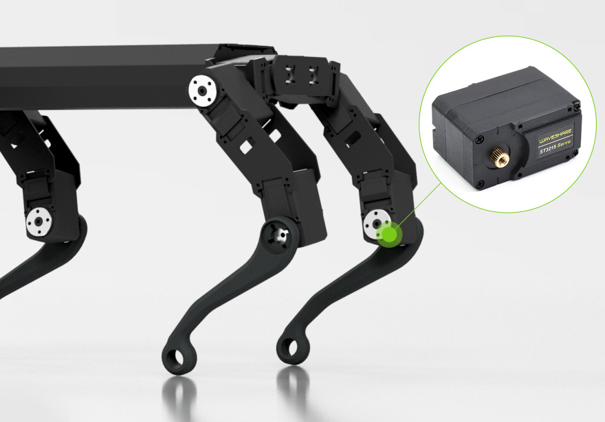
* images here are for reference ONLY
High Precision, Longer Lifetime
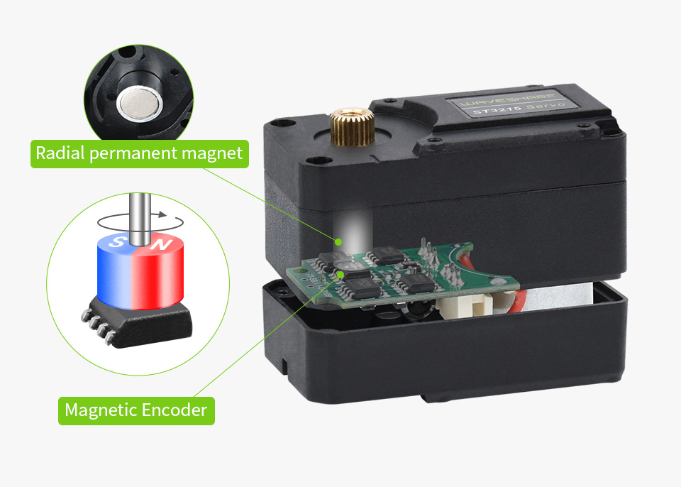
Adopts 12-bit high-precision magnetic encoding angle sensor. Compared with the potentiometer, the angle is enlarged to 360°, and the resolution is increased by 4 times. Since there is a gap and no friction between the magnetic encoder and the radial magnet, the lifetime of the servo is effectively extended.
The speed and acceleration values can be set, and the motion effect is softer
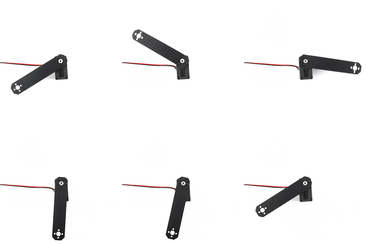
Actual Effect
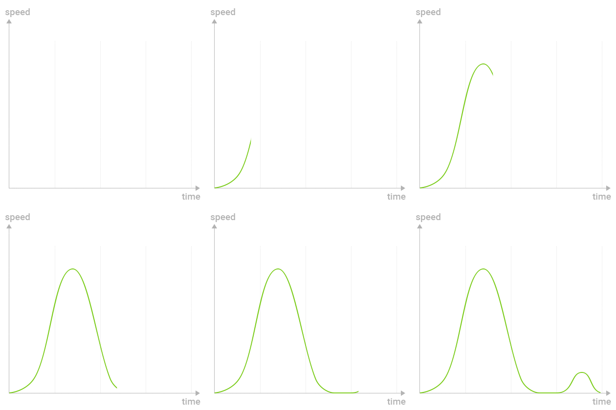
Motion Effect Diagram
The case adopts higher intensity engineering plastics, dual shaft and low profile design, shortening the plane spacing of the double-shaft servo wheel, and the overall structure is more compact, which can make the appearance of the product more beautiful.

360° installation at any position, one button to set the current position as middle position. Easy to install

1. In the default program, a hotspot will be created automatically after the servo driver board is turned on. Use your mobile phone to connect to this hotspot, open the browser, and enter the IP address to enter the control interface.
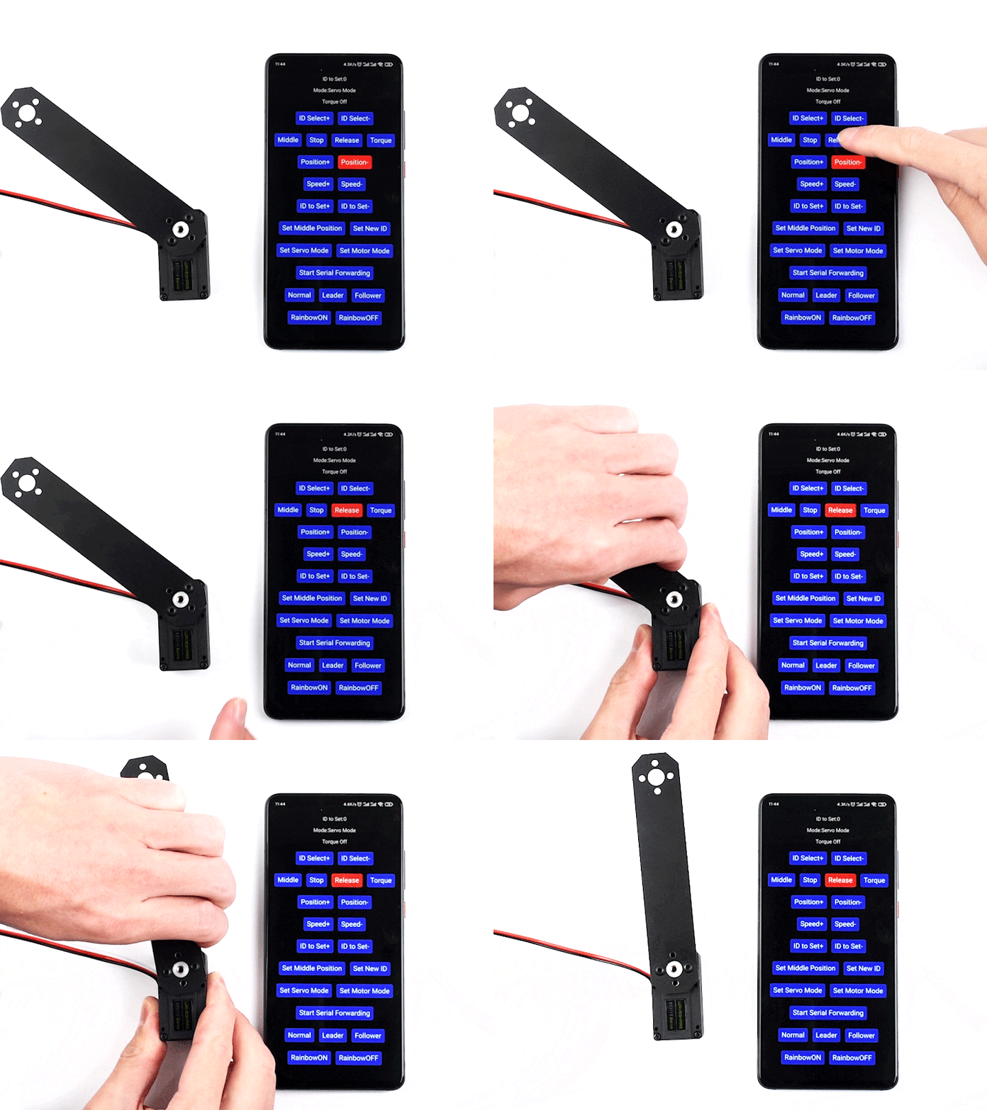
2. Click Release to unlock, then turn the servo to the middle position where you need to set

3. Click Set Middle Position then comfirm.
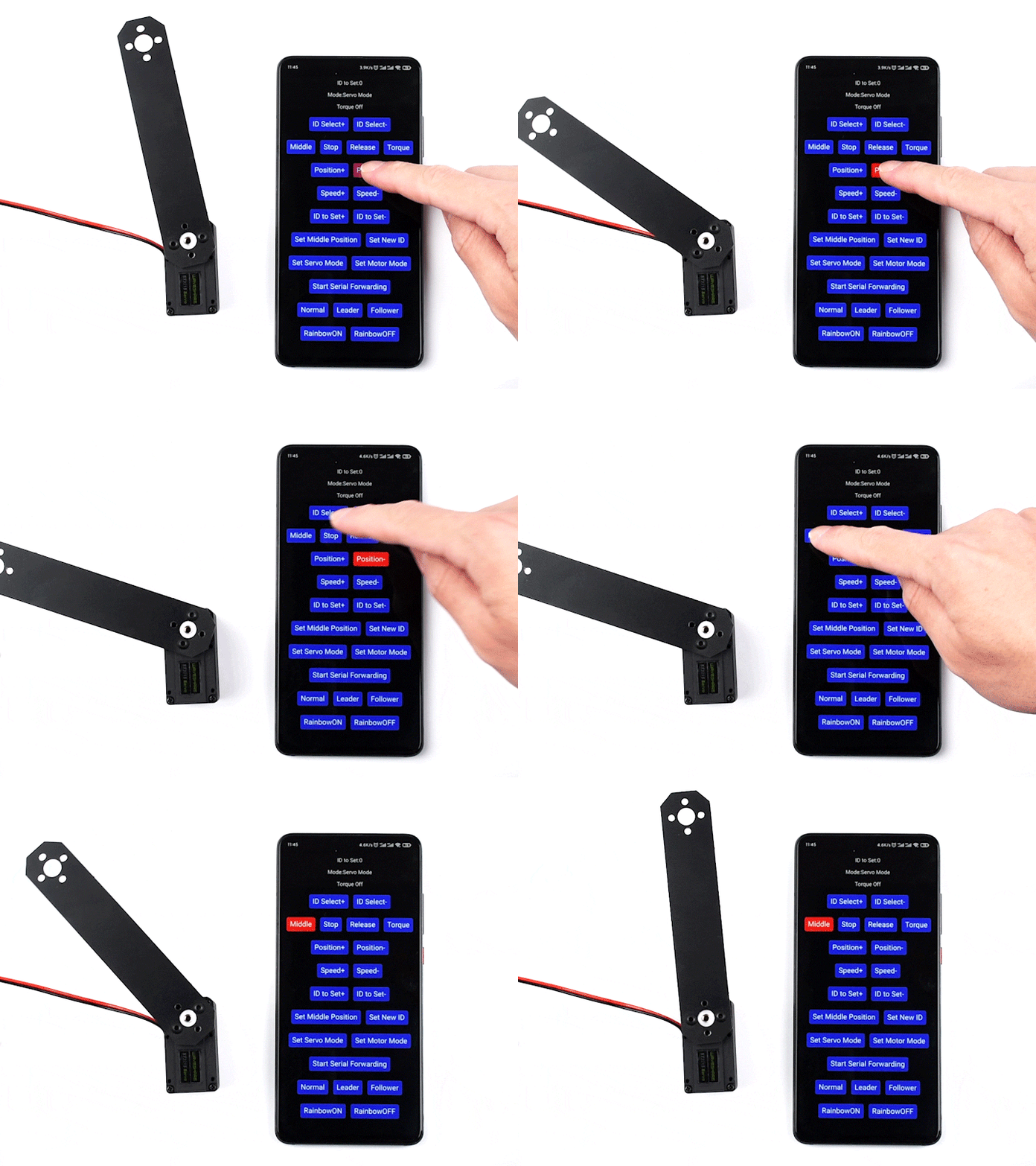
4. Turn the servo to any angle, then click Middle, and the servo will automatically return to the middle position initially set.
The Servos Will Provide Various Feedback Like Position, Load, Speed,
And Input Voltage In Real Time
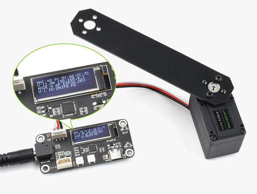
* images here are for reference ONLY
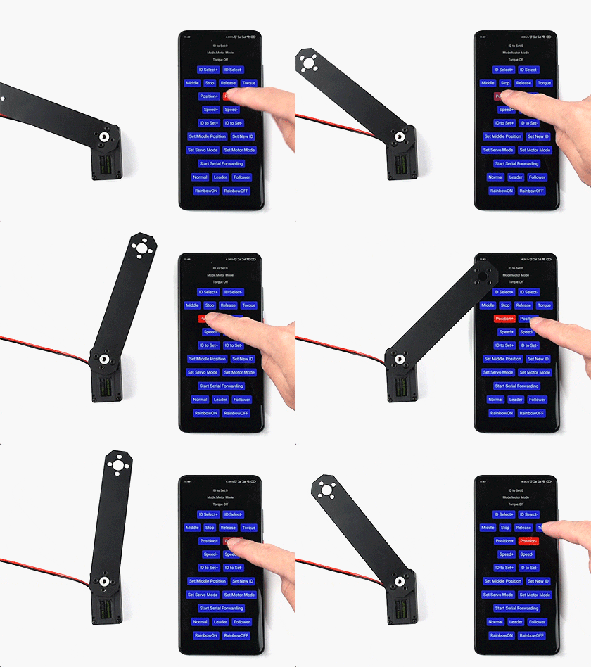
precise rotation angle control on servo mode

continuous rotation on motor mode
* images here are for reference ONLY
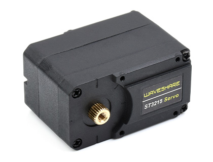
Nylon and fiberglass case
Improved heat-resistance, size stability, rigidity, and mechanical performance
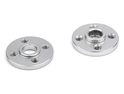
High strength aluminum servo wheels
Using T6061 aluminum alloy, good corrosion-resistance

High precision copper and steel gears
Ingenious combination of the two, lower operating noise, better stability and mechanical performance
We provide the open-source web control demo of the servo driver board and a secondary development tutorial, which can be directly used for remote setting and remote control of the servo. At the same time, we also provide a 3D model for you to build your own project quickly
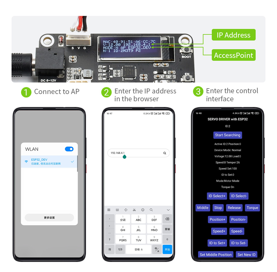


* Resources for different product may vary, please check the wiki page to confirm the actually provided resources.
| Product | Voltage | Control Method | Precision | NO-LOAD SPEED | Continuous Rotation | LOCKED-ROTOR TORQUE * | LOCKED-ROTOR CURRENT | Range | Feedback |
|---|---|---|---|---|---|---|---|---|---|
| WP90 | 4.8 ~ 7.4 | PWM | ≤2° | 0.1sec/60° | - | 2.3kg.cm | 1.0A | 180° | - |
| SC09 | 4.8 ~ 8.4 | TTL | 300°/1024 | 0.1sec/60° | √ | 2.3kg.cm | 1.0A | 300° | √ |
| SC15 | 4.8 ~ 8.4 | TTL | 180° / 1024 | 0.16 sec / 60° | √ | 15kg.cm | 1.5A | 180° | √ |
| ST3020 | 6 ~ 14.0 | TTL | 360° / 4096 | 0.167sec / 60° | √ | 25kg.cm | 2.7A | 360° | √ |
| ST3215 | 6 ~ 12.6 | TTL | 360° / 4096 | 0.222 sec / 60° | √ | 30kg.cm | 2.7A | 360° | √ |
| ST3025 | 6 ~ 12.6 | TTL | 360° / 4096 | 0.117sec / 60° | √ | 40kg.cm | 4.4A | 360° | √ |
| ST3235 | 6 ~ 12.6 | TTL | 360° / 4096 | 0.222sec/60° | √ | 30kg.cm | 2.7A | 360° | √ |
| CF35-12 | 9.0 ~ 12.6 | TTL | 360° / 4096 | 0.222sec/60° | √ | 35kg.cm | 2.8A | 360° | √ |
| RSBL35-24-HS | 9.0 ~ 24.0 | RS485 | 360° / 4096 | 0.087sec/60° | √ | 35kg.cm | 1.8A | 360° | √ |
| RSBL45-24 | 9.0 ~ 24.0 | RS485 | 360° / 4096 | 0.142sec/60° | √ | 45kg.cm | 2.3A | 360° | √ |
| RSBL85-12 | 9.0 ~ 12.0 | RS485 | 360° / 4096 | 0.167sec/60° | √ | 85kg.cm | 7.9A | 360° | √ |
| RSBL85-24 | 9.0 ~ 24.0 | RS485 | 360° / 4096 | 0.154sec/60° | √ | 85kg.cm | 5.6A | 360° | √ |
| RSBL120-24 | 9.0 ~ 24.0 | RS485 | 360° / 4096 | 0.2sec/60° | √ | 120kg.cm | 4A | 360° | √ |
* the Locked-rotor torque is measured at the typical voltage of each servo, please refer to the documentation in the wiki for more details


