Photo Interrupter Sensor
| ||
Overview
Photo Interrupter Sensor is a light occlusion interrupt sensor, which is often used in smart car speed measurement.
Principle: This product adopts a WYC-H206 slot photoelectric sensor, one end is an infrared transmitting tube, and the other end is an infrared receiving. When there is a block, the infrared receiving end cannot receive infrared and outputs a high level, which is triggered by inverting Schmitt. The device becomes low-level output, and the signal indicator is on at the same time. The use of the Schmitt trigger makes the output signal more stable, with good waveform and no jitter.
Features
- Infrared detection, eliminating the interferences of external stray light.
- Schmitt trigger, stable waveform, and signals.
- Signal output indicator (while breaking the beam, outputs a low level, and the indicator lights up).
Specification
- Power: 3.3V ~ 5V
- Dimension: 26.8mm × 15mm × 18.7mm
- Mounting holes size: 3mm
- Gap width: 6mm
Pinouts
| PIN | Description |
| DOUT | Digital data output |
| GND | Power ground |
| VCC | 3.3V-5V |
Get Started at Pico
If you are the first time o use the Pico, you need to first learn how to get started at the Pico before you run other examples.
The Pico supports C and the Micropython which requires different firmware.
In most of the examples archives (Demo codes), we provide a Micropython firmware (uf2 file), we recommend you to use the provided firmware to test the board. Because the codes may run abnormally with different firmware.
If the board is tested to be workable, you can also download the newest firmware from Raspberry Pi and do further programming.
- If you want to use C codes, please refer to the C/C++ Guides
- If you want to use Micropython codes, please refer to the Micropython Guides.
- The link of the newest Micropython firmware of Pico
- Official Guides of Raspberry Pi Pico
Hardware Connection
| Sensor | Pico | Description |
|---|---|---|
| VCC | 3.3V | Power input |
| GMD | GND | Power ground |
| DOUT | GP22 | Digital data output |
Download examples
Use Raspberry Pi as the host device. Open a terminal and run the following commands to download the example.
sudo apt-get install p7zip-full
cd ~
sudo wget  https://files.waveshare.com/upload/f/f6/Photo_Interrupter_Sensor_Demo.7z
7z x Photo_Interrupter_Sensor_Demo.7z -o./Photo_Interrupter_Sensor_Demo
cd ~/Photo_Interrupter_Sensor_Demo
cd Pico/c/build/
Examples
C codes
- Go into the c directory:
cd ~/Photo_Interrupter_Sensor_Demo/Pico/c/build
- Add the path of the SDK.
export PICO_SDK_PATH=../../pico-sdk
- Note that if the path of your SDK is different, you need to modify the command and use the correct path to export
- Generate Makefile and build.
cmake ..
make -j9
- After building, a uf2 file is generated.
- Press and hold the button of Pico, connect it to Raspberry Pi then release the button.
- Copy/Drag the uf2 file to the portable disk (RPI-RP2) recognized.
cp main.uf2 /media/pi/RPI-RP2/
Micropython codes
Use in Windows
- 1. Press and hold the BOOTSET button on the Pico board, connect the Pico to the USB port of the computer through the Micro USB cable, and release the button after the computer recognizes a removable hard disk (RPI-RP2).
- 2. Copy the rp2-pico-20210418-v1.15.uf2 file in the python directory to the recognized removable disk (RPI-RP2).
- 3. Open Thonny IDE (Note: Use the latest version of Thonny, otherwise there is no Pico support package, the latest version under Windows is v3.3.3).
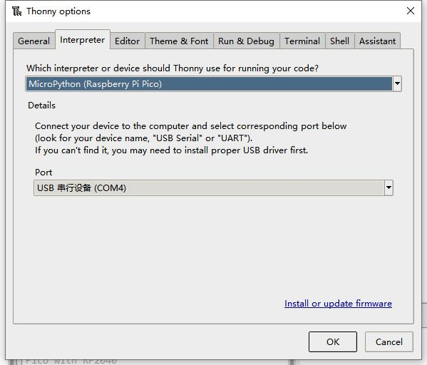
- 4. Click Tools -> Settings -> Interpreter, and select Pico and the corresponding port as shown in the figure.
- 5. File -> Open -> the corresponding .py file, click to run, as shown in the following figure:

This demo provides a simple program...
Use in Raspberry Pi
- Flash the Micropython firmware first.
- Open the Thonny IDE (Menu -> Programming -> Thonny Python IDE).
- 【Optional】If the Thonny IDE in the Raspberry Pi is not the new version that supports Pico, please upgrade it first.
sudo apt upgrade thonny
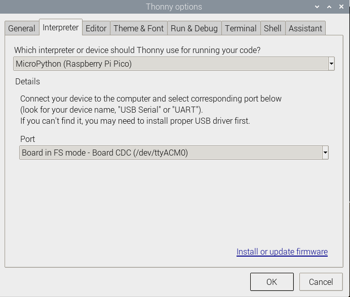
- Configure Interpreter, choose Tools -> Options... -> Interpreter, choose MicroPython (Raspberry Pi Pico) and the ttyACM0 port.
- Click File -> Open.. and browser the Micropython codes (Photo Interrupter Sensor.py) to run the codes.
Expected result
When a barrier is placed above the sensor, the signal indicator will turn on and the serial port will say "ON" or else the serial port will say "OFF". The STM32 examples are based on the STM32F103RBT6 and the STM32H743. The connection provided below is based on the STM32F103RB. If you need to use other STM32 boards, you may need to change the hardware connection and port the code yourself.
STM32
Hardware connection
| Sensor | STM32 | Description |
|---|---|---|
| VCC | 3.3V | Power input |
| GMD | GND | Power ground |
| DOUT | PA4 | Digitial data output |
Examples
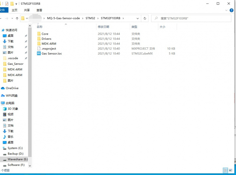
The examples are developed based on the HAL libraries. Download the demo codes to your PC. Unzip and find the STM32 project from Photo_Interrupter_Sensor_Demo\STM32\STM32F103RB\MDK-ARM.
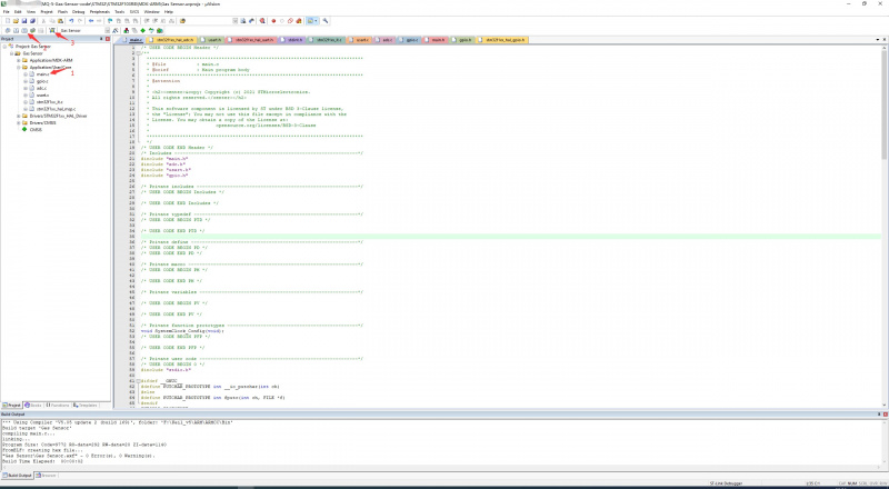
- Open the Photo Interrupter Sensor.uvprojx file by Keil.
- Open main.c and recompile to download:
- After downloading, run SSCOM to connect the Photo Interrupter module, and you can see the real-time sensor status.
When the sensor is blocked by an object, the signal indicator on the module lights up and the serial port shows "ON", otherwise the signal indicator lights up, and the serial port shows "OFF".
This demo has been tested on Arduino UNO, you can directly connect it to Arduino UNO according to the table below.
The Arduino example is written for the Arduino UNO. If you want to connect it to other Arduino boards, you may need to change the connection.
Arduino
Hardware connection
| Sensor | Arduino | Description |
|---|---|---|
| VCC | 5V | Power input |
| GMD | GND | Power ground |
| DOUT | D2 | Digital data output |
Examples
- Download the demo codes to your PC and unzip.
- Install the Arduino IDE on your PC.
- Go into Photo_Interrupter_Sensor_Demo/Arduino/Photo_Interrupter_Sensor.
- Run the Photo_Interrupter_Sensor .ino file .
- Select the correct Board and the Port.
- Build the project and upload it to the board.
- Open the serial monitor of the Arduino IDE or the SSCOM software and check the serial data.
- Result: When the sensor is blocked by an object, the signal indicator on the module is on, and the serial port displays "ON", otherwise the signal indicator is off, and the serial port displays "OFF".
Resources
Support
Technical Support
If you need technical support or have any feedback/review, please click the Submit Now button to submit a ticket, Our support team will check and reply to you within 1 to 2 working days. Please be patient as we make every effort to help you to resolve the issue.
Working Time: 9 AM - 6 PM GMT+8 (Monday to Friday)


