MarsBoard AM335X Package A
| ||
| ||
| ||
Getting Ready
The MarsBoard AM335X Package A contains 2 Shields, of which drivers are embedded in this firmware: Click here to download the firmware (MarsBoard-AM335X-Package-A-TF-4GB-Debian-7.5-HDMI-2015.06.20-v2.1.img.7z). Please first write the firmware image to your MarsBoard and then enjoy these development kits. Note: location of API source code for the following examples: /home/debian/API.
How to write OS to a TF card
- Unzip the firmware.
- A file archiver software, such as 7-Zip, is required to unzip the corresponding image file.
- Format your TF card.
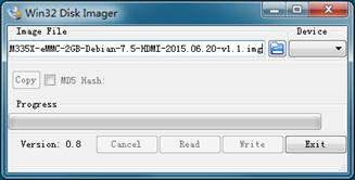
- Write the system firmware.
Boot up from the TF card system
Note: a 5V/2A adapter is used for power supply.
- Insert the TF card into the TF card socket;
- Set the boot up switch (hereafter BOOT) to “SD”;
For easy debugging, Connect the DEBUG port on SIM-AM335X board to your PC with a mini-USB cable. - Power up to start the system.
Login
- Power up and start the Debian OS.
User name: debian
password: temppd - Enable "root" user:
sudo -s
- Execute the script to install the examples:
./cape
- All the following examples are run under root permission.
Examples
Note:
- Location of API source code for the following examples: /home/debian/API.
Examples for Accessory Shield
- Connect Accessory Shield to AM335X Adapter and then plug them to the mother board.
- Run the following command with root permission.
- You can press Ctrl + C to terminate process.
1) Key test
- Run the command:
test_key
Push or press the joystick and the corresponding keys will be listed on the terminal, e.g.
- key1 is pressed code ------->B
- key1 is pressed code ------->D
- key1 is pressed code ------->C
- key1 is pressed code ------->A
- key1 is pressed code ------->CTR
2) LM75 test
- Run the command:
test_lm75
Current temperature will be printed, e.g.
- temperature:22.375000
3) ADC test
- Run the command:
test_adc 0
Adjust the potentiometer knob and AD value of Channel 0 will be printed, e.g.
- Channel 0 current value is 2201
4) OLED test
- Run the command:
test_oled
OLED screen will work and display a picture. 5) Buzzer test
- Make the buzzer sound with the command:
test_gpio_buzzer 0
- Stop the buzzer sound with the command:
test_gpio_buzzer 1
6) RTC test
- Show system date time:
date
- Set system date time:
date 020809302014.23
- Set the hardware clock of RTC module:
hwclock -w -f /dev/rtc1
If read time error, execute the following command:
- Show the hardware clock of RTC module:
hwclock –r –f /dev/rtc1
- Synchronize the hardware clock to system date time:
hwclock –s –f /dev/rtc1
Power off and reboot then execute the following command:
hwclock -r -f /dev/rtc1
hwclock -s -f /dev/rtc1
7) ADXL345 test
- Show the position status of the board with the command:
test_adx345
- Move the board and the printed logs will be changed.
Examples for Analog Test Shield
- Connect Analog Test Shield to AM335X Adapter and then plug them to the mother board.
- Run the following command with root permission.
- You can press Ctrl + C to terminate process.
1) DAC test
- Place jumpers on DAC-SPK and DAC-LED.
- Execute the command:
test_dac
- You can adjust the Analog Potentiometer to change the audio frequency.
- LED flashed.
- Adjust the Volume knob to change volume of the speaker.
2) PWM test:
- Place jumpers on DAC-SPK, PWM-LED and D11-PWM.
- Execute the command:
test_gpio_pwm 100
- Audio frequency and LED brightness are changeable according to the parameter following test_gpio_pwm.
- Note: The PWM here is generated by GPIO.
3) ADC test
- Place jumpers on ADC-A0
- Execute the command:
test_adc 0
- Adjust the Analog knob and the printed value will be changed.
Resources
Peripherals Schematic
- Accessory Shield Schematic
- Analog Test Shield Schematic
- AM335X LCD Board Schematic
- AM335X Adapter Schematic
MarsBoard AM335X Schematic
Firmware
Development tools for the AM335X
- CP2102 Driver
- Win32DiskImager, a Windows program for saving and restoring images from removable drives.
- 7-Zip, an open source file archiver
- Panasonic SD Formatter
- PuTTY, a free and open-source terminal emulator, serial console and network file transfer application.
Cross compiler tool chain
Technical Support
If you need technical support or have any feedback/review, please click the Submit Now button to submit a ticket, Our support team will check and reply to you within 1 to 2 working days. Please be patient as we make every effort to help you to resolve the issue.
Working Time: 9 AM - 6 PM GMT+8 (Monday to Friday)


