4inch TFT Touch Shield
| ||
Introduction
4inch Arduino Touch Shield
| More |
Arduino
How to Connect
Note: The following picture is the connection diagram of the 2.8-inch TFT screen and Arduino uno, but this product is connected in exactly the same way.


Hardware Connection
- If the Arduino board has an ICSP interface, set the SPI Config switch on the display module to the ICSP direction (by default) (the company's Arduino UNO motherboard has an ICSP interface, just plug it in directly.).
- If the Arduino board does not have an ICSP interface, set the SPI Config switches on the display module to SCLK\D13, MISO\D12, MOSI\D11 respectively.
Install Compile Software
Run the Program
- Unzip the compressed package, open the folder, and open the Arduino folder, you can see three project folders LCD_Show, LCD_ShowBMP, LCD_Touch.
- This product uses the same LCD control chip and touch panel control chip as the 3.5-inch TFT screen of the same series of our company, so the code is completely compatible. The following takes 3.5-inch TFT as an example to introduce.
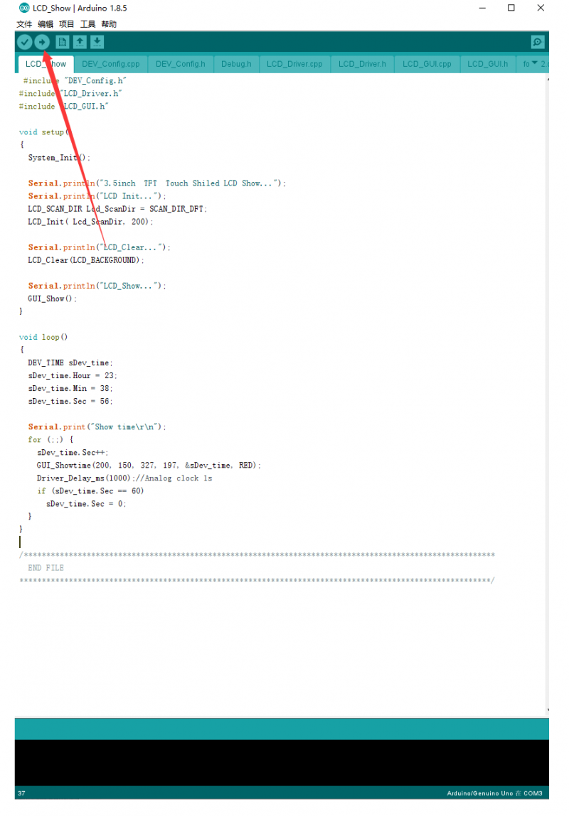
- First, open the LCD_Show.ino file in the LCD_Show folder directly, then select the development board model Arduino UNO.

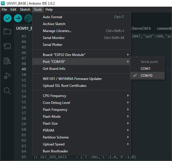
Select the corresponding COM port.

Then click to compile and upload.

Program Description
LCD_Show can display colorful patterns with different shapes and times. LCD_ShowBMP is for displaying the picture in BMP, and LCD_Touch is for using the touching function.
The display controller used in this product is ILI9486, and we need to initialize the controller through the SPI communication protocol, and the initialization functions are written in LCD_Driver.cpp.
It can be seen that there are in LCD_Show.ino:
System_Init();//System initialization, configure serial port baud rate, SPI and related pins, etc.<br/>
   LCD_SCAN_DIR Lcd_ScanDir = SCAN_DIR_DFT; //Set the scan mode <br/>
   LCD_Init( Lcd_ScanDir, 200);//Initialize the screen, and pass the scanning mode and backlight brightness.<br/>
The function functions related to the screen display are written in LCD_GUI.cpp. The function of each function and the parameters passed are explained in the source code. You can call it directly when you need to use it.
- Draw dots:
void GUI_DrawPoint(POINT Xpoint, POINT Ypoint, COLOR Color,
                   DOT_PIXEL Dot_Pixel, DOT_STYLE DOT_STYLE)
- Draw lines (solid or dashed):
void GUI_DrawLine(POINT Xstart, POINT Ystart, POINT Xend, POINT Yend,
                  COLOR Color, LINE_STYLE Line_Style, DOT_PIXEL Dot_Pixel)
- Draw a rectangle (hollow or solid):
void GUI_DrawRectangle(POINT Xstart, POINT Ystart, POINT Xend, POINT Yend,
                       COLOR Color, DRAW_FILL Filled, DOT_PIXEL Dot_Pixel)
- Draw a circle (hollow or solid):
void GUI_DrawCircle(POINT X_Center, POINT Y_Center, LENGTH Radius,
                    COLOR Color, DRAW_FILL  Draw_Fill , DOT_PIXEL Dot_Pixel)
- Display characters:
void GUI_DisChar(POINT Xpoint, POINT Ypoint, const char Acsii_Char,
                 sFONT* Font, COLOR Color_Background, COLOR Color_Foreground)
- Display string:
void GUI_DisString_EN(POINT Xstart, POINT Ystart, const char * pString,
                      sFONT* Font, COLOR Color_Background, COLOR Color_Foreground )
- Show numbers:
void GUI_DisNum(POINT Xpoint, POINT Ypoint, int32_t Nummber,
                sFONT* Font, COLOR Color_Background, COLOR Color_Foreground )
- Display time:
void GUI_Showtime(POINT Xstart, POINT Ystart, POINT Xend, POINT Yend,
                  DEV_TIME *pTime, COLOR Color)
- Before using LCD_ShowBMP to display pictures, first copy the pictures in the PIC folder in the data to the root directory of the SD card (you should understand that in the root directory, that is to save the pictures directly to the SD card, do not put them in any subfolders folder.).
- Then insert the SD card into the SD card slot on the back of the screen to start the download program verification.
- It should be noted that the SD card should be in the FAT format, and the picture should be 480*320 pixels with a 24-bit color depth. BMP format
- Here is an explanation. This demo shows that the BMP picture first reads the picture data in the BMP format in the SD card through the SPI protocol, and then displays the data as an image.
In LCD_ShowBMP.ino:
SD_Init();//SD card initialization
LCD_ShowBMP();//Show BMP picture
- These functions are all written in LCD_Bmp.cpp. In fact, the image data in BMP format with a specific file name is read from the SD card, and then the display function written by us is called to re-express the data as an image.
- No matter which platform this method is on, the principle is similar. Interested friends can check the relevant information and study the relevant code carefully.
- In LCD_Touch.ino:
TP_Init( Lcd_ScanDir );//The touchpad is initialized, and the passed parameter is the scan mode.
   TP_GetAdFac();//Calibrate the screen.
   TP_Dialog();//Clear the screen.
   TP_DrawBoard();//Open the drawing board.
After running this demo, there are five colors on the right side of the screen. Black is the default color in the system, and you can touch it to choose the brush color. Click AD button, and click the red "+" to calibrate the screen with the prompts. Click the right corner "CLEAR" to clear the drawing board.
The functions related to the touch screen are written in LCD_Touch.cpp, and their functions and the purpose of passing parameters are explained.
The program provides a pixel size of
   Width 5, Height 8    font8
   Width 7, Height 12    font12
   Width 11, Height 16    font16
   Width 14, Height 20    font20
   Width 17, Height24    font24
Font library in five sizes
- If you need characters in different sizes and fonts, you can generate the font library you want according to the font extraction software provided in the Resource.
- In fact, you can also use Image2Lcd image modulo software to convert images of different sizes and formats into array data, and then use the functions we wrote to display them.
- The data sheets of all control chips are given in the information for your reference. If you want to know more about why the underlying functions are written like this, go to the data sheets and look at them!
STM32
The demo has been tested on XNUCLEO-F103RB, just insert XNUCLEO-F103RB as shown below. The model of XNUCLEO-F103RB is STM32F103RBT6. If you need to port the program, please connect it according to the actual pin and the schematic diagram.
How to Insert
The connection diagram is as follows (click to enlarge):
Note: The following picture is the connection diagram of the 2.8-inch TFT screen and XNUCLEO-F103RB, but this product is connected in exactly the same way.


Software Description
The demos are developed based on the HAL library. Download the program, find the STM32 program file directory, and open STM32\XNUCLEO-F103RB\lcd4in-demo\MDK-ARM\ lcd4in-demo.uvprojx.
This product uses the same LCD control chip and touch panel control chip as the 3.5-inch TFT screen of the same series of our company, so the code is completely compatible. The following takes a 3.5-inch TFT as an example to introduce.

Click to compile and download one by one.

Program Description
After running the demo, it displays some characters and patterns at first, then displays four pictures, and finally displays the touch sketchpad function. Actually, three projects in the Arduino platform code are integrated in the main function, we place the three main functions in sequence and place TP_DrawBoard(); in an infinite loop to achieve the above functions.
GUI_Show();
LCD_Show_bmp(Bmp_ScanDir , Lcd_ScanDir);
TP_DrawBoard();
It uses the same driver and program framework as the Arduino platform. For the location of different functions, please refer to the Arduino tutorial.
Before using LCD_ShowBMP to display pictures, copy the pictures in the PIC folder in the data to the root directory of the SD card, and then insert the SD card into the SD card slot on the back of the screen to start the download program verification.
- It should be noted here that the SD card should be in the FAT format, and the picture should be 480*320 pixels with 24-bit color depth and BMP format.
The program provides a pixel size of:
Width 5, Height 8     font8
Width 7, Height 12    font12
Width 11, Height 16   font16
Width 14, Height 20   font20
Width 17, Height24    font24
Font library in five sizes:
- If you need characters of different sizes and fonts, you can generate the font library you want according to the font extraction software provided in the data.
- In fact, you can also use Image2Lcd image modulo software to convert images of different sizes and formats into array data, and then use the functions we wrote to display them.
- The data sheets of all control chips are given in the information for your reference. If you want to know more about why the underlying functions are written like this, go to the data sheets and look at them!
Resources
Documentation
Datasheet
3D Drawings
Development Resource
FAQ
{{{5}}}
Support
Technical Support
If you need technical support or have any feedback/review, please click the Submit Now button to submit a ticket, Our support team will check and reply to you within 1 to 2 working days. Please be patient as we make every effort to help you to resolve the issue.
Working Time: 9 AM - 6 PM GMT+8 (Monday to Friday)
