Template: Color Sensor Arduino Guide
The Arduino example is written for the Arduino UNO. If you want to connect it to other Arduino boards, you may need to change the connection.
Working with Arduino
Hardware connection
| Sensor | Arduino | Description |
|---|---|---|
| VCC | 5V | Power input |
| GMD | GND | Power ground |
| S0 | D6 | Combined with S1, select output frequency scaling |
| S1 | D5 | Combined with S2, select output frequency scaling |
| S2 | D4 | Combined with S3, select output frequency scaling |
| S3 | D3 | Combined with S2, select output frequency scaling |
| OUT | D2 | Read the output frequency of RGB |
| LED | GP16 | Control the states of 4 LED indicators |
Examples
- Download the demo codes to your PC and unzip.
- Install the Arduino IDE on your PC.
- Go into Color-Sensor-code/Arduino/Color_Sensor.
- Run the Color_Senosr.ino file.
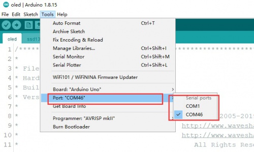
- Select the correct Board and the Port.
- Build the project and upload it to the board.
- Open the serial monitor of the Arduino IDE or the SSCOM software and check the serial data.
Operation and Result
1. Place the white paper 1CM above the four bright white LED side of the sensor (hereinafter referred to as the front).
2. Power on the development board. At this time, the LED port is connected to a high level, and the four high-bright white LEDs are on.
3. Wait for more than 2 seconds after power on (white balance is being adjusted at this time).
4. After the adjustment, please put the sensor facing the object to be measured, and the serial port outputs the corresponding RGB data.
Refer to the color comparison table to know the detected color.
Precautions
1. Avoid the interference of external light during color recognition, otherwise it will affect the result of color recognition.
Place the Color Sensor and light source etc. in a closed, non-reflective box for testing.
2. White balance adjustment is required every time the Color Sensor module is restarted or the light source is replaced.


