Serial Expansion HAT
| ||
Introduction
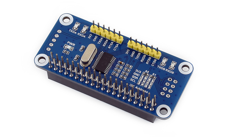
Serial Expansion HAT for Raspberry Pi, I2C Interface, Provides 2-ch UART and 8 GPIOs
Features
- Raspberry Pi connectivity, compatible with Raspberry Pi Zero/Zero W/Zero WH/2B/3B/3B+.
- Onboard SC16IS752 expands 2-ch UART and 8 programmable GPIO through I2C, no extra pin required.
- It is stackable up to 16 modules by setting the address jumper, which means up to 32-ch UART.
- Onboard multi LEDs for indicating the UART working status.
- Reserved I2C control pins, which allow working with other control boards.
- Comes with online development resources and manuals (examples in C and Python).
Specification
- Operating voltage: 3.3V
- Expansion chip: SC16IS752
- Control interface: I2C
- Dimension: 65mm × 30mm
- Mounting hole size: 3.0mm
Hardware
The SC16IS752 is an I2C-bus/SPI bus interface to a dual-channel high-performance UART. It also provides the application with 8 additional programmable I/O pins. This module uses the I2C interface by default, and its device address is hardware configurable by A0 and A1.
PINOUT
| PIN | Description |
| 3V3 | 3.3V |
| GND | Ground |
| TXDA | Transmit pin of CHA |
| RXDA | Receive pin of CHA |
| RTSA | Receive request of CHA |
| CTSA | Transmit request of CHA |
| TXDB | Transmit pin of CHB |
| RXDB | Receive pin of CHB |
| RTSB | Receive request of CHB |
| CTSB | Transmit request of CHB |
LED
PWR: Power indicator
TXDA: Transmit indicator of CHA
RXDA: Receive indicator of CHA
TXDB: Transmit indicator of CHB
RXDB: Receive indicator of CHB
I2C Address Configuration
A0, A1 are used to control the I2C address of device, you can change them by soldering 0ohm resistors acccording the table:
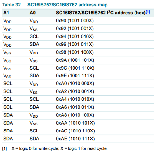
Please refer to datasheet:Page39.
The I2C addresses in the table are 8 bits, however, the actual address is 7 bits, you need to right-shift one bit to get the actual I2C address. For example, if you connect A1 and A0 to Vdd, the address of the module is 0x90 according to the table, to get the actual address you need to right-shift the data from 1001 000X to 100 1000, which is 0x48.
【Note】This module A0 and A1 are default welded to 3.3V, with I2C address 0x48
In theory, you can connect 32 devices to the same developer board by changing addresses.
If you bought the old version which is produced before 20191231, the interrupt pin is connected to the GPIO of the PI directly, you can only wire the devices for stacking multi-devices.
If you buy the new version which is produced after 10291231, the interrupt pin is configurable by soldering resistors. Supports up to 5 devices by changing the pin, if you want to stack more than five devices, you need to wire them by cable.
Working with Raspberry Pi
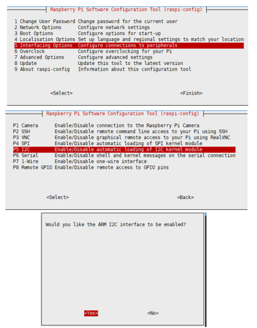
Enable I2C Interface
Open a terminal and run the following commands:
sudo raspi-config
Choose Interfacing Options -> I2C -> Yes.
Reboot Raspberry Pi:
sudo reboot
Install Library
If you use bookworm system, only the lgpio library is available, bcm2835 and wiringPi libarary cannot be installed or used. Please note that the python library does not need to install, you can directly run the demo.
BCM2835
#Open the Raspberry Pi terminal and run the following command
wget http://www.airspayce.com/mikem/bcm2835/bcm2835-1.71.tar.gz
tar zxvf bcm2835-1.71.tar.gz
cd bcm2835-1.71/
sudo ./configure && sudo make && sudo make check && sudo make install
# For more, you can refer to the official website at: http://www.airspayce.com/mikem/bcm2835/
WiringPi
#Open the Raspberry Pi terminal and run the following command
cd
sudo apt-get install wiringpi
#For Raspberry Pi systems after May 2019 (earlier than that can be executed without), an upgrade may be required:
wget https://project-downloads.drogon.net/wiringpi-latest.deb
sudo dpkg -i wiringpi-latest.deb
gpio -v
# Run gpio -v and version 2.52 will appear, if it doesn't it means there was an installation error

# Bullseye branch system using the following command:
git clone https://github.com/WiringPi/WiringPi
cd WiringPi
. /build
gpio -v
# Run gpio -v and version 2.70 will appear, if it doesn't it means there was an installation error
lgpio
wget https://github.com/joan2937/lg/archive/master.zip
unzip master.zip
cd lg-master
sudo make install
#for more details, you can refer to https://github.com/gpiozero/lg
python
sudo apt-get install python-dev
sudo apt-get install python-rpi.gpio
sudo apt-get install python-smbus
Configuration
- Append the line below to /boot/config.txt file:
sudo nano /boot/config.txt
# addr should be the same as the actual setting of A0A1, default 0X48
dtoverlay=sc16is752-i2c,int_pin=24,addr=0x48
# reboot
sudo reboot
- After rebooting, you can execute the command: ls /dev to check if SC16IS752 has been enabled to kernel:

GPIOchip is the driver of 8 GPIO. (It may be gpiochip3 or gpiochip2 according to different versions of OS), ttysc0 and ttysc1 is the driver of serial ports.
You cannot directly stack the devices for multi-connecting because they use the same interrupt pin.
You need to wire the devices by cable or change the resistors, and modify the config.txt file:
dtoverlay=sc16is752-i2c,int_pin=xx,addr=0x48
xx is the actual BCM code of the interrupt pin.
Testing
Download demo codes
wget https://files.waveshare.com/upload/b/ba/Serial_Expansion_HAT_code.tar.gz
tar zxvf Serial_Expansion_HAT_code.tar.gz
sudo chmod 777 -R Serial_Expansion_HAT_code
cd Serial_Expansion_HAT_code
Test Serial port
- c codes, the baud rate is default 115200.
#Send data via Serial A
cd c/uart/send
make clean
make
sudo ./uart_send
#Receive data via Serial B
cd c/uart/receive/
make clean
make
sudo ./uart_receive
- Test:
You can connect the TXDA to RXDB, RXDA to TXDB, and open a terminal one is set for transmitting codes and another is set for receiving codes.
Expected result: After running the code. Receiver: keep receiving and print data received; Sender: send characters.

If you test the device with an external serial device, the GND should be connected for usage properly.
- Python, default baud rate 115200
cd python/Uart/
#Send data by Serial A
sudo python send.py
#Receive data by Serial B
sudo python receive.py
Expect result: After running the code. Receiver: keep receiving and print data received; Sender: send characters.
Test GPIO
- c
cd c/gpio/
make clean
make
sudo ./main
After running the demo, the program will flip the level of GPIO0. If you connect an LED light to GPIO0, you will find that the LED light flashes.
- python
cd python/GPIO
sudo python gpio.py
Expected result: The level of the GPIO0 is toggled five times, GPIO1 is set as input, and you can connect GPIO1 to 3.3V or GND to check the data.
Multi-devices
If you want to stack multi-devices for use more Serial ports, please follow the guides below:
Install i2c-tools and check the i2c address:
sudo apt-get install i2c-tools
Check the i2c address with the following command:
sudo i2cdetect -y 1
If there is only one Serial Expansion HAT, it should be as the figure:

The address is UU but not 0x48, which means that the driver has been enabled in OS and you can find ttySC* devices in the /dev directory.
If you want to stack another Serial Expansion HAT, you need to modify the address setting and INT pin of the second board first. For example: INT PIN -> P23, I2C Address: A0 -> GND:
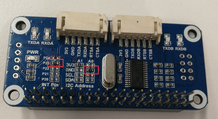
After modifying, you can stack the boards and run the following commands.
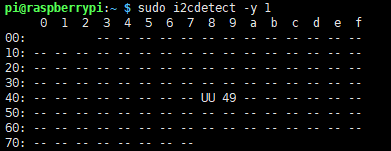
The new board is recognized as 0x49. You also need to add a setting line to the config.txt file:
sudo nano /boot/config.txt
Add the following line and save:
dtoverlay=sc16is752-i2c,int_pin=23,addr=0x49
sudo reboot
Check the devices with commands:
![]()
Because only five INT settings are available onboard, you can only stack five boards with the method above. If you want to connect more devices, you need to change and connect them by cable.
Resources
Documents
Demo Codes
FAQ
{{{5}}}
The Raspberry Pi is installed with the mainstream Ubuntu system and can be used;
You cannot directly change the config.txt file in the Raspberry Pi. When you open the boot folder on the Raspberry Pi, the config.txt file is an empty file, which generally cannot be changed;
Instead, use the SD card of the Raspberry Pi to read and change the config.txt file under the computer (or other hosts that can recognize the SD card) through the card reader.
{{{5}}}
Support
Technical Support
If you need technical support or have any feedback/review, please click the Submit Now button to submit a ticket, Our support team will check and reply to you within 1 to 2 working days. Please be patient as we make every effort to help you to resolve the issue.
Working Time: 9 AM - 6 PM GMT+8 (Monday to Friday)

