
RP2350-GEEK
Overview
| ||

Introduction
RP2350-GEEK is a development board designed for geeks by Waveshare. It comes with a USB-A port, 1.14-inch LCD screen, TF card slot, and other peripherals. Depending on the firmware used, it can provide SWD interface, UART interface, and I2C interface, offering endless possibilities for your projects.
Features
- RP2350 microcontroller chip designed by Raspberry Pi
- Adopts unique dual-core and dual-architecture design, equipped with dual-core ARM Cortex-M33 processor and dual-core Hazard3 RISC-V core processor, flexible clock running up to 150 MHz
- Built-in 520KB of SRAM and 16MB of on-chip Flash
- Onboard 1.14inch 240×135 pixels 65K color IPS LCD display
- Onboard 3PIN SWD interface for connecting to the target board to be debugged
- Standard CMSIS-DAP interface, applicable for most ARM-based microcontrollers
- Works with OpenOCD and other tools supporting CMSIS-DAP
- Adopts the Raspberry Pi 3PIN Debug Connector Specification
- Onboard 3PIN UART interface for USB serial adapter
- Onboard 4PIN I2C port for the testing target board
- Equipped with plastic case and cables
- Open-source firmware, more convenient to upgrade
Dimensions

Pico Getting Started
Firmware Download
- MicroPython Firmware Download

- C_Blink Firmware Download

Basic Introduction
MicroPython Series
Install Thonny IDE
In order to facilitate the development of Pico/Pico2 boards using MicroPython on a computer, it is recommended to download the Thonny IDE
- Download Thonny IDE and follow the steps to install, the installation packages are all Windows versions, please refer to Thonny's official website for other versions
- After installation, the language and motherboard environment need to be configured for the first use. Since we are using Pico/Pico2, pay attention to selecting the Raspberry Pi option for the motherboard environment

- Configure MicroPython environment and choose Pico/Pico2 port
- Connect Pico/Pico2 to your computer first, and in the lower right corner of Thonny left-click on the configuration environment option --> select Configture interpreter
- In the pop-up window, select MicroPython (Raspberry Pi Pico), and choose the corresponding port


Flash Firmware
- Click OK to return to the Thonny main interface, download the corresponding firmware library and burn it to the device, and then click the Stop button to display the current environment in the Shell window
- Note: Flashing the Pico2 firmware provided by Micropython may cause the device to be unrecognized, please use the firmware below or in the package
- How to download the firmware library for Pico/Pico2 in windows: After holding down the BOOT button and connecting to the computer, release the BOOT button, a removable disk will appear on the computer, copy the firmware library into it
- How to download the firmware library for RP2040/RP2350 in windows: After connecting to the computer, press the BOOT key and the RESET key at the same time, release the RESET key first and then release the BOOT key, a removable disk will appear on the computer, copy the firmware library into it (you can also use the Pico/Pico2 method)

MicroPython Series Tutorials
【MicroPython】 machine.Pin class function details
【MicroPython】machine.PWM class function details
【MicroPython】machine.ADC class function details
【MicroPython】machine.UART class function details
【MicroPython】machine.I2C class function details
【MicroPython】machine.SPI class function details
【MicroPython】rp2.StateMachine class function details
C/C++ Series
For C/C++, it is recommended to use Pico VS Code for development. This is a Microsoft Visual Studio Code extension designed to make it easier for you to create, develop, and debug projects for the Raspberry Pi Pico series development boards. No matter if you are a beginner or an experienced professional, this tool can assist you in developing Pico with confidence and ease. Here's how to install and use the extension.
- Official website tutorial: https://www.raspberrypi.com/news/pico-vscode-extension/
- This tutorial is suitable for Raspberry Pi Pico, Pico2 and the RP2040 and RP2350 series development boards developed by Waveshare
- The development environment defaults to Windows11. For other environments, please refer to the official tutorial for installation
Install VSCode
-
First, click to download pico-vscode package, unzip and open the package, double-click to install VSCode

Note: If vscode is installed, check if the version is v1.87.0 or later


Install Extension
-
Click Extensions and select Install from VSIX

-
Select the package with the vsix suffix and click Install

-
Then vscode will automatically install raspberry-pi-pico and its dependency extensions, you can click Refresh to check the installation progress

-
The text in the right lower corner shows that the installation is complete. Close VSCode


Configure Extension
-
Open directory C:\Users\username and copy the entire .pico-sdk to that directory

-
The copy is completed

-
Open vscode and configure the paths for the Raspberry Pi Pico extensions

The configuration is as follows:Cmake Path: ${HOME}/.pico-sdk/cmake/v3.28.6/bin/cmake.exe Git Path: ${HOME}/.pico-sdk/git/cmd/git.exe Ninja Path: ${HOME}/.pico-sdk/ninja/v1.12.1/ninja.exe Python3 Path: ${HOME}/.pico-sdk/python/3.12.1/python.exe


New Project
-
The configuration is complete, create a new project, enter the project name, select the path, and click Create to create the project
To test the official example, you can click on the Example next to the project name to select
-
The project is created successfully

-
Select the SDK version

-
Select Yes for advanced configuration

-
Choose the cross-compilation chain, 13.2.Rel1 is applicable for ARM cores, RISCV.13.3 is applicable for RISCV cores. You can select either based on your requirements

-
Select Default for CMake version (the path configured earlier)

-
Select Default for Ninjaversion

-
Select the development board

-
Click Complie to compile

-
The uf2 format file is successfully compiled


Import Project
- The Cmake file of the imported project cannot have Chinese (including comments), otherwise the import may fail
-
To import your own project, you need to add a line of code to the Cmake file to switch between pico and pico2 normally, otherwise even if pico2 is selected, the compiled firmware will still be suitable for pico

set(PICO_BOARD pico CACHE STRING "Board type")

Update Extension
-
The extension version in the offline package is 0.15.2, and you can also choose to update to the latest version after the installation is complete


Arduino IDE Series
Install Arduino IDE
-
First, go to Arduino official website to download the installation package of the Arduino IDE.

-
Here, you can select Just Download.

-
Once the download is complete, click Install.

Notice: During the installation process, it will prompt you to install the driver, just click Install


Arduino IDE Interface
-
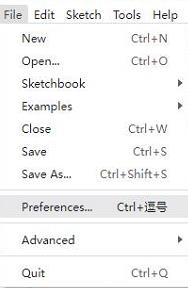
After the first installation, when you open the Arduino IDE, it will be in English. You can switch to other languages in File --> Preferences, or continue using the English interface.

-
In the Language field, select the language you want to switch to, and click OK.


Install Arduino-Pico Core in Arduino IDE
-
Open the Arduino IDE, click on the file in the top left corner, and select Preferences
-
Add the following link to the attached board manager URL, and then click OK
https://github.com/earlephilhower/arduino-pico/releases/download/4.0.2/package_rp2040_index.json
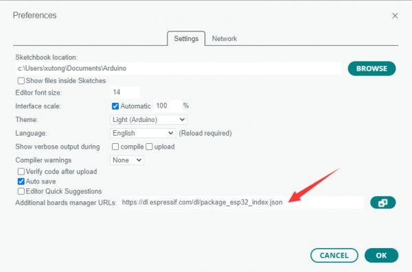
Note: If you already have an ESP32 board URL, you can use a comma to separate the URLs as follows:https://dl.espressif.com/dl/package_esp32_index.json,https://github.com/earlephilhower/arduino-pico/releases/download/4.0.2/package_rp2040_index.json
-
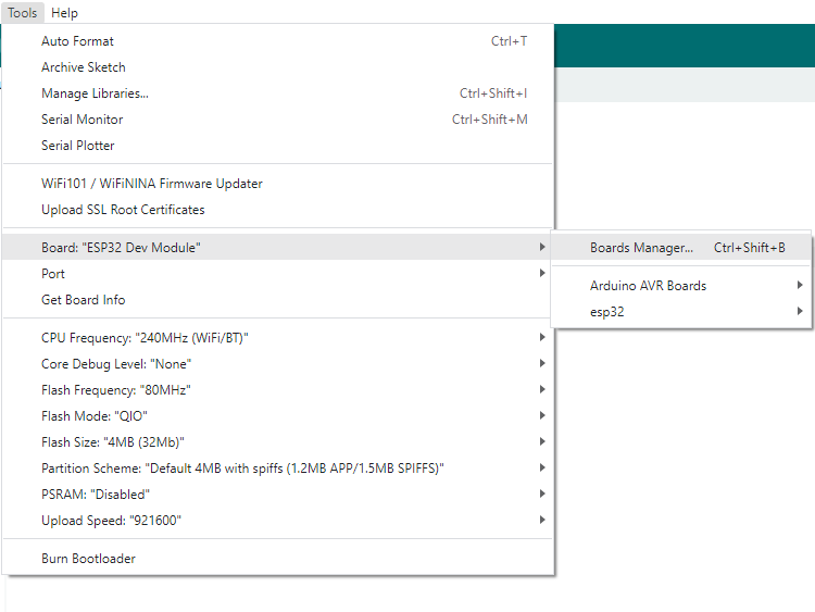
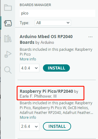
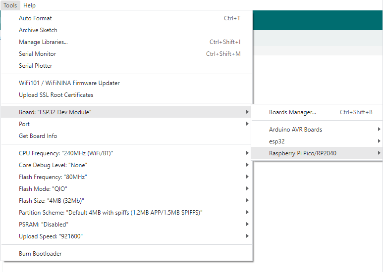
Click Tools > Development Board > Board Manager > Search pico, as my computer has already been installed, it shows that it is installed


Upload Demo at the First Time
-
Press and hold the BOOTSET button on the Pico board, connect the pico to the USB port of the computer via the Micro USB cable, and release the button after the computer recognizes a removable hard disk (RPI-RP2).
- Download the program and open D1-LED.ino under the arduino\PWM\D1-LED path
-
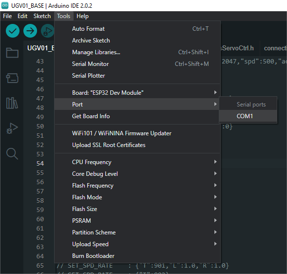
Click Tools --> Port, remember the existing COM, do not click this COM (the COM displayed is different on different computers, remember the COM on your own computer)
-
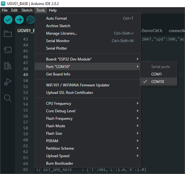
Connect the driver board to the computer using a USB cable. Then, go to Tools > Port. For the first connection, select uf2 Board. After uploading, when you connect again, an additional COM port will appear
-
Click Tools > Development Board > Raspberry Pi Pico > Raspberry Pi Pico or Raspberry Pi Pico 2
- After setting it up, click the right arrow to upload the program


- If issues arise during this period, and if you need to reinstall or update the Arduino IDE version, it is necessary to uninstall the Arduino IDE completely. After uninstalling the software, you need to manually delete all contents within the C:\Users\[name]\AppData\Local\Arduino15 folder (you need to show hidden files to see this folder). Then, proceed with a fresh installation.
Open Source Demos
MircoPython video demo (github)
MicroPython firmware/Blink demos (C)
Raspberry Pi official C/C++ demo (github)
Raspberry Pi official micropython demo (github)
Arduino official C/C++ demo (github)
Demo
C/C++ Demo
01-LCD
- LCD refreshes an image and waits for 2.5 seconds
- LCD refreshes GUI demo
02-picoprobe
- This demo is based on the open-source program picoprobe
- The RP2350-GEEK runs the picoprobe demo, which will emulate a USB TO SWD and USB TO UART device
- Using the UART interface as a USB to serial tool, it can be used for device communication
- Using the SWD interface as a debugging tool, when used with openocd, it can debug most ARM chips
- For more information, please refer to the "PicoProbe Tutorial" below
03-FATFS
- The demo is based on the open-source program no-OS-FatFS-SD-SDIO-SPI-RPi-Pico
- The demo implements a command-line interface similar to busybox or DOS. It can mount a TF card, create and view files, and so on. The command “help” can be used to view all available commands


- Note that the TF card file format is FAT32
Micropython Demo
01-LCD
How to Use
- Upload all py and bmp files under the file to the RP2350-GEEK via thonny upload


Running Result
- LCD displays the GUI screen, waits for a few seconds, and then displays the bmp image
02-SD
How to Use
- Upload all py files under the file to the RP2350-GEEK via thonny and reset


Running Result
- After the RP2350-GEEK is reset, it will automatically mount the TF to the SD file according to the boot.py program

- Double-click to open the SD folder, and you can see the files stored in the TF card


LVGL Demos
C
Example Demonstration
The effect displayed in this example is to show an image through LVGL.
Demo Introduction
This example is used to test the LVGL widdet interaction and style beautification, etc.. For specific development of LVGL, please refer to LVGL development documentation.
Implement Function
- In this example, DMA is used to transfer color data to the SPI bus, reducing CPU utilization, and controlling CPU usage to less than 50% and memory usage to less than 35% during simple interactions.
- The example system clock is 200MHz. The peripheral clock frequency for SPI is set to match the system clock, and the LVGL library's dual buffer mechanism is utilized. Data transfer occurs in one buffer while the other buffer is rendering, ensuring smooth animation.
- This example displays an image through LVGL, demonstrating the simple use of LVGL widget.
Compile and Run
- Windows
- Refer to Windows Environment Setup Tutorial to complete the environment setup
- Open VS 2022 -> Tool -> Command Line -> Developer Powershell
- Set the absolute address of pico-sdk as PICO_SDK_PATH, for example, set pico-sdk address as "D:\pico\pico-sdk"
setx PICO_SDK_PATH "D:\pico\pico-sdk"
- Download the demo, enter the source code directory, if the build directory already exists, you can go directly into it. If not, you can create this directory:
mkdir build
cd build
- Execute cmake, automatically generate the Makefile file:
cmake -G "NMake Makefiles" ..
- Execute nmake to generate the executable file, and input the following content in the terminal:
nmake
After compilation, it will generate a .uf2 formatted file. - Press the onboard boot key, connect the board to the USB interface of the PC through a Micro USB cable. And then release the key, the PC will identify the pico as a removable driver. Finally, you need to copy the compiled file in .uf2 format to Pico.
- Ubuntu
- Refer to Chapter 2. The SDK of Pico Getting Started to complete the environment setup
- Open a terminal, set the value of the environment variable PICO_SDK_PATH to the absolute path of pico-sdk, for example, if my pico-sdk path is "/home/pico/pico-sdk"
nano ~/.bashrc
#Add the following content at the last line
export PICO_SDK_PATH="/home/pico/pico-sdk"
- After setting, save and exit. The configuration takes effect
source ~/.bashrc
- Download the demo, enter the source code directory, if the build directory already exists, you can go directly into it. If not, you can create this directory:
mkdir build
cd build
- Execute cmake, it will generate Makefile file:
cmake ..
- Execute nmake to generate the executable file, and input the following content in the terminal:
nmake
After compilation, it will generate a .uf2 formatted file. - Press the onboard boot key, connect the board to the USB interface of the PC through a Micro USB cable. And then release the key, the PC will identify the pico as a removable driver. Finally, you need to copy the compiled file in .uf2 format to Pico.
Source Code Analysis
Source Code Structure
- The source code of the LVGL library is at lib/lvgl of the project file folder, and the version used is "8.1". For secondary development, please refer to the development documentation corresponding to the used version.
- The related settings for the LVGL library are at examples/inc/lv_conf.h of the project file folder, where you can set display refresh rates, system usage data, and so on.

- The application code for the LVGL library is located in the project folder at examples/src/LVGL_example.c.


LVGL Initialization
Before using LVGL image library, you need to initialize LVGL.
- The initialization function for the LVGL library
- Demo location: examples/src/LVGL_example.c
- Implementation function: Mainly used to initialize the hardware and structure variables required for LVGL.
LVGL_Init();
- LVGL library core initialization
- Demo location: examples/src/LVGL_example.c
/*2.Init LVGL core*/
lv_init();
LVGL Run
The LVGL library calls the heartbeat function lv_tick_inc at regular intervals to notify LVGL of the elapsed time so that LVGL can update its internal time state and handle time-related tasks such as animations, timers, etc. The lv_task_handler function also needs to be called in the loop of the main function so that LVGL can handle events and tasks in time to ensure that the user interface responds and refreshes.
- LVGL heartbeat interface
- Demo location: examples/src/LVGL_example.c
- Implementation method: It is necessary to ensure that the priority of lv_task_handler is lower than the priority of lv_tick_inc. Therefore, in this example, lv_tick_inc is called within the timer callback function.
//Timer callback function called every 5ms
add_repeating_timer_ms(5, repeating_lvgl_timer_callback, NULL, &lvgl_timer);

static bool repeating_lvgl_timer_callback(struct repeating_timer *t)
{
    lv_tick_inc(5);
    return true;
}
- LVGL Task Processor
- Demo location: examples/src/LCD_XinXX_LVGL_test.c
- Implementation method: To handle LVGL tasks, you need to regularly call lv_timer_handler(), in this example, it is called in the loop of the main function.
int main()
{
    ...
    while(1)
    {
      lv_task_handler();
      DEV_Delay_ms(5);
      ...
    }

}
LVGL Display
To implement LVGL display, you must initialize a display driver and set the various properties of the display driver, such as color format, draw buffer, rendering mode, and display callback function. At each LV_DISP_DEF_REFR_PERIOD (set in lv_conf.h), LVGL detects if something has happened on the UI that needs to be redrawn. For example, a button is pressed, a chart is changed, an animation occurs, etc. When redrawing is needed, LVGL calls the display callback function to complete the drawing of the image in the refresh area.
- LVGL display refreshing rate
- Demo location: examples/inc/lv_conf.h
- Setting method: In the lv_conf.h file, you can also set the display buffer refresh rate. You can modify this definition to change the screen refresh time.
#define LV_DISP_DEF_REFR_PERIOD 10 // Unit: ms, here is 10ms
- LVGL display color setting
- Demo location: examples/inc/lv_conf.h
- Purpose of setting: Since the pixel color storage method constructed by the lv_color_t structure in its default state does not match the data to be transmitted in this example, direct transmission would result in color discrepancies in the displayed image.
#define LV_COLOR_16_SWAP 1
- LVGL display related variable definition
- Demo location: examples/src/LVGL_example.c
- Implementation function: Define the display driver disp_drv, draw the buffer disp_buf. This example implements a double buffering mechanism, with the drawing buffer composed of buffers buf0 and buf1, both set to half the size of the screen display area, which can reduce jagged edges during large area refreshing while effectively improving screen refresh rate; when using a single buffer, it is best to set it to 10% of the screen display area, which can effectively reduce system usage but may result in noticeable jagged edges during large area refresh of image.
static lv_disp_drv_t disp_drv;
static lv_disp_draw_buf_t disp_buf;
static lv_color_t buf0[DISP_HOR_RES * DISP_VER_RES/2];
static lv_color_t buf1[DISP_HOR_RES * DISP_VER_RES/2];
- LVGL display device registration
- Demo location: examples/src/LVGL_example.c
- Implementation function: According to the design requirements, improve the core structure variables of the LVGL library, initialize the display driver disp_drv, and set the drawing buffer, which is a simple array used by LVGL to render screen content. Once the rendering is ready, the content of the draw buffer will be sent to the display using the disp_drv_flush_cb function set in the display driver.
/*3.Init LVGL display*/
lv_disp_draw_buf_init(&disp_buf, buf0, buf1, DISP_HOR_RES * DISP_VER_RES / 2);
lv_disp_drv_init(&disp_drv);
disp_drv.flush_cb = disp_flush_cb;
disp_drv.draw_buf = &disp_buf;
disp_drv.hor_res = DISP_HOR_RES;
disp_drv.ver_res = DISP_VER_RES;
lv_disp_t *disp= lv_disp_drv_register(&disp_drv);
- LVGL display callback function
- Demo location: examples/src/LVGL_example.c
- Implementation function: Mainly complete the drawing of the image in the refresh area.
void disp_flush( lv_disp_drv_t *disp_drv, const lv_area_t *area, lv_color_t *color_p )
Parameters:
    lv_disp_drv_t *disp_drv: Displays driver structure pointers, which contain information about the display and function pointers. This parameter is often used to notify you that a refresh is complete
    const lv_area_t *area  : Region structure pointer, containing the position information of the area to be refreshed. In this demo, you can use it for creating TFT display window.
    lv_color_t *color_p    : Color structure pointer, indicating the color data to be displayed in the refresh area. In this demo, it reads the address as DMA input to transmit data to the SPI bus and completes the image drawing
- LVGL display callback function implementation
- Demo location: examples/src/LVGL_example.c
- Implementation method: In this example, to maximize the reduction of processor utilization, DMA is used for color data transmission. color_p is set as the read address, and the SPI bus output data register is set as the write address.
static void disp_flush_cb(lv_disp_drv_t * disp, const lv_area_t * area, lv_color_t * color_p)
{
    LCD_SetWindows(area->x1, area->y1, area->x2+1, area->y2+1);
    DEV_Digital_Write(LCD_DC_PIN, 1);
    DEV_Digital_Write(LCD_CS_PIN, 0);
    dma_channel_configure(dma_tx,
                          &c,
                          &spi_get_hw(LCD_SPI_PORT)->dr,
                          color_p, // read address
                          ((area->x2 + 1 - area-> x1)*(area->y2 + 1 - area -> y1))*2,
                          true);
}
- LVGL refresh completion notification implementation
- Demo location: examples/src/LVGL_example.c
- Implementation function: The LVGL core needs to be notified after each image refresh is completed, so that LVGL can prepare the next refresh image for rendering.
- Implementation method: In this example, the completion of the DMA transmission is notified in the interrupt service function for LVGL image refresh. If a blocking notification mechanism is used, it is not possible to utilize the double buffering mechanism to increase the refresh rate.
static void dma_handler(void)
{
    if (dma_channel_get_irq0_status(dma_tx)) {
        dma_channel_acknowledge_irq0(dma_tx);
        DEV_Digital_Write(LCD_CS_PIN, 1);
        lv_disp_flush_ready(&disp_drv);
    }
}
LVGL Widget Layout
In LVGL, we can create various user interfaces. The basic components of the interface are objects, also called widgets, such as buttons, labels, images, lists, charts, or text areas. In a interface, we can create multiple widgets simultaneously and set their positions, sizes, parent objects, styles, and event handlers and other basic properties.
- LVGL widget initialization
- Demo location: examples/src/LVGL_example.c
- Implementation function: It primarily used for stylized widgets and layout widgets.
void Widgets_Init(void);
- LVGL create tile
- Demo location: examples/src/LVGL_example.c
- Implementation function: A Tile view is a container object whose elements, called tiles, can be arranged in a grid format. Users can navigate between tiles by swiping. Call lv_tileview_add_tile(tileview, row_id, col_id, dir) to create a new tile at row_id row and col_id column. dir can be LV_DIR_LEFT/RIGHT/TOP/BOTTOM/HOR/VER/ALL or a value to move to the adjacent tile in the given direction by sliding.
//Create a tile at (0,0) with support for sliding down to (0,1)
tile1 = lv_tileview_add_tile(tv, 0, 0, LV_DIR_BOTTOM);
- LVGL create widget
- Demo location: examples/src/LVGL_example.c
- Implementation function: To create a widget, different widgets need to use different function interfaces, you can choose the parent object to create it.
//Create a widget where tab1 is the parent object of the key, which can be replaced with a widget such as list, title, etc. that can have child objects
sw = lv_switch_create(tab1);
- Alignment positioning of LVGL widget
- Demo location: examples/src/LVGL_example.c
- Implementation function: Enable a widget to be offset and positioned based on a reference point. The widget aligns to the center of the offset reference point widget.
- Alignment standard: The LVGL library supports both internal and external alignments. By default, the upper-left corner is the origin, the leftward as the positive horizontal direction, and the downward as the positive vertical direction.
//Position the btn widget 45 pixels to the left from the center point
lv_obj_align(sw, LV_ALIGN_CENTER, -45, 0);

- LVGL widget to adjust font size
- Demo location: examples/inc/lv_conf.h and examples/src/LVGL_example.c
- Implementation function: In actual use, an interface may need to use multiple font sizes. Multiple font sizes can be enabled in lv_conf.h and the default font size can be set. When setting the font size, it is necessary to stylize the widget so that it can be rendered according to the set style. The lv_obj_add_style function can be used to render various parts of the widget in different states.
#define LV_FONT_MONTSERRAT_16 1                                // Enable font 16
#define LV_FONT_MONTSERRAT_18 1                                // Enable font 18
#define LV_FONT_DEFAULT &lv_font_montserrat_18                 // Set the default font size as 18

static lv_style_t style_label;
lv_style_init(&style_label);                                   // Initialize style
lv_style_set_text_font(&style_label, &lv_font_montserrat_16);  // Set the font size as 16
lv_obj_add_style(label,&style_label,0);                        // Set label theme style
- LVGL widget event handling
- Demo location: examples/src/LVGL_example.c
- Implementation function: In LVGL, you can add an event handler callback function to a widget so that when the widget is clicked, scrolled, redrawn, etc., it triggers an event and enters the event handler callback function. Call lv_obj_add_event_cb(obj, event_cb, filter, user_data) function in the program to add the event filter handling function event_cb for the widget obj, when the widget obj triggers the filter event, the system will automatically call the event_cb function. The last parameter is a pointer to any custom data available in the event.
//Add handler function sw_event_cb for event LV_EVENT_VALUE_CHANGED to widget sw
lv_obj_add_event_cb(sw, sw_event_cb,LV_EVENT_VALUE_CHANGED,NULL);
Python
Example Demonstration
The effect displayed in this example is to show an image through LVGL.
Demo Introduction
This demo is for testing LVGL widget interaction, style design and so on. The version used is 9.1. As the development document of LVGL V9 does not provide Python example, you can refer to LVGL LVGL development documentation.
Implement Function
- The example system clock is 230MHz. The peripheral clock frequency for SPI is set to match the system clock, and the LVGL library's dual buffer mechanism is utilized. Data transfer occurs in one buffer while the other buffer is rendering, ensuring smooth animation.
- This example displays an image through LVGL, demonstrating the simple use of LVGL widget.
Compile and Run
- Operation steps
- Before starting to use, it is necessary to set up an integrated development environment Thonny Python IDE (Windows version V3.3.3)
- Download the demo, and press the onboard boot key, connect the board to the USB interface of the PC through a Micro USB cable. And then release the key, the PC will identify the pico as a removable driver. Finally, you need to copy the compiled file in .uf2 format to Pico.
- Open Thonny, upload the examples and lib directories to the development board

- Open the LCD_1in14_LVGL_test.py file under the examples directory, please refer to the steps below to run the demo

- Firmware building
- Envitonment building: only test on Ubuntu 22.04
- Github: lv_micropython
- Refer to Raspberry Pi Pico port to compile
- Firmware generation path: lv_micropython/ports/rp2/build-PICO/firmware.uf2


Source Code Analysis
Source Code Structure
- For LVGL library source code, you can refer to lv_micropython
- The related setting of the LVGL library is at lv_micropython/lib/lv_bindings/lv_conf.h file folder, which sets the refreshing frequency of the display, system occupied data and so on.
- The application code for the LVGL library is located in examples/src/LVGL_example.c and lib/LVGL.py folders of the project folder.


LVGL Initialization
Before using LVGL image library, you need to import the LVGL library and initialize the LVGL objects
- Import an LVGL library
- Demo location: lib/LVGL.py
- Implementation function: Import LVGL library and use alias "lv" to facilitate calling its functions
import lvgl as lv
- Create an LVGL object
- Demo location: examples/LCD_1in14_LVGL_test.py
- Implementation function: Create an LVGL object and pass in LCD and TSC objects as parameters
# Init LVGL
LVGL(LCD=LCD,TSC=TSC)
- LVGL initialization
- Demo location: lib/LVGL.py
- Code description: LVGL core initializes the initialization function located in the LVGL class, which is automatically called when the LVGL object is created
if not lv.is_initialized(): lv.init()
LVGL Run
The LVGL library periodically calls the heartbeat interface function lv.tick_inc to inform LVGL of the past time so that LVGL can update its internal time state to handle time-related tasks such as animations, timers, and so on. In addition, the lv.task_handler function needs to be called so that LVGL can handle events and tasks in time to ensure that the user interface responds and refreshes.
- LVGL Running interface
- Demo location: lib/LVGL.py
- Implementation method: Create an event_loop object. In the initialization function of this class, we create a timer. The timer will automatically call the heartbeat interface function and event handler function within a set time interval. The time interval for the call can be adjusted by passing the freq parameter, such as lv_utils.event_loop(freq=200), which defaults to 40 ms.
# Create event loop if not yet present
if not lv_utils.event_loop.is_running(): self.event_loop=lv_utils.event_loop()
- LVGL heartbeat interface
- Demo location: lib/lv_utils.py
- Implementation method: You need to make sure that the priority of lv.task_handler is lower than that of lv.tick_inc , so in this case, lv.tick_inc is called in the timer callback function.
#Timer callback function called every 5ms
self.timer.init(mode=Timer.PERIODIC, period=self.delay, callback=self.timer_cb) // In this case, self.delay = 5

def timer_cb(self, t):
    lv.tick_inc(self.delay)
    if self.scheduled < self.max_scheduled:
        try:
            micropython.schedule(self.task_handler_ref, 0)
            self.scheduled += 1 # The number of tasks being processed has increased
        except:
            pass
- LVGL Task Processor
- Demo location: lib/lv_utils.py
- Implementation method: To handle LVGL tasks, you need to call lv.task_handler at regular intervals, in this case after calling lv.tick_inc in the timer callback function.
def task_handler(self, _):
    try:
        if lv._nesting.value == 0:
            lv.task_handler()
            if self.refresh_cb: self.refresh_cb()
        self.scheduled -= 1 # The number of tasks being processed has decreased
    except Exception as e:
        if self.exception_sink:
            self.exception_sink(e)
LVGL Display
To implement LVGL display, you must initialize a display driver and set the various properties of the display driver, such as color format, draw buffer, rendering mode, and display callback function. At each LV_DEF_REFR_PERIOD (set in lv_conf.h), LVGL detects if something has happened on the UI that needs to be redrawn. For example, a button is pressed, a chart is changed, an animation occurs, etc. When redrawing is needed, LVGL calls the display callback function to complete the drawing of the image in the refresh area.
- LVGL display refreshing rate
- Demo location: lv_micropython/lib/lv_bindings/lv_conf.h
- Setting method: In lv_conf.h, you can modify LV_DEF_REFR_PERIOD to change the refresh time of the screen.
#define LV_DEF_REFR_PERIOD 10 // Unit: ms, here is 10ms
- LVGL display related variable definition
- Demo location: lib/LVGL.py
- Implementation function: The sizes of buf0 and buf1 are set to 33% of the screen display area to implement the LVGL dual buffer mechanism, which reduces the appearance of jagged edges during large area refresh of screen updates while effectively increasing the screen refresh rate; when using a single buffer, it is best to set it to 10% of the screen display area, which can effectively reduce system usage but may result in noticeable jagged edges during large area refresh of image.
# Init LVGL display
buf1 = lv.draw_buf_create(self.LCD.width, self.LCD.height // 3 , color_format, 0)
buf2 = lv.draw_buf_create(self.LCD.width, self.LCD.height // 3, color_format, 0)
- LVGL display device registration
- Demo location: lib/LVGL.py
- Implementation function: According to the design requirements, improve the core structure variables of the LVGL library, initialize the display driver disp_drv, and set the drawing buffer, which is a simple array used by LVGL to render screen content. Once the rendering is ready, the content of the draw buffer will be sent to the display using the disp_drv_flush_cb function set in the display driver.
self.disp_drv = lv.display_create(self.LCD.width, self.LCD.height) # Create a display driver object and set the width and height
self.disp_drv.set_color_format(color_format) # Set color format to RGB565
self.disp_drv.set_draw_buffers(buf1, buf2)   # Set the drawing buffer
self.disp_drv.set_render_mode(lv.DISPLAY_RENDER_MODE.PARTIAL) # Set the rendering mode to partial refresh mode
self.disp_drv.set_flush_cb(self.disp_drv_flush_cb) # Set display callback function
- LVGL display callback function
- Demo location: lib/LVGL.py
- Implementation function: Mainly complete the drawing of the image in the refresh area.
def disp_drv_flush_cb(self,disp_drv,area,color_p)
Parameters:
    disp_drv : Displays driver structure pointers, which contain information about the display and function pointers. This parameter is often used to notify you that a refresh is complete
    area     : Region structure pointer, containing the position information of the area to be refreshed. In this demo, you can use it for creating TFT display window.
    color_p     : Color structure pointer, indicating the color data to be displayed in the refresh area. In this demo, it reads the address as DMA input to transmit data to the SPI bus and completes the image drawing
- LVGL display callback function implementation
- Demo location: lib/LVGL.py
- Implementation method: In this example, to maximize the reduction of processor utilization, DMA is used for color data transmission. color_p is set as the read address, and the SPI bus output data register is set as the write address. The code is long and only shows part of it, please download the demo to view the full code.
def disp_drv_flush_cb(self,disp_drv,area,color_p):
    ......
    self.rgb565_swap_func(data_view, size)  # Convert color format

    self.LCD.setWindows(area.x1, area.y1, area.x2+1, area.y2+1) # Set LVGL interface display position

    ...... # DMA configuration is executed immediately

    while self.dma.active(): # Wait for DMA to be idle
            pass

    self.disp_drv.flush_ready() # Notify LVGL that data transfer is complete
LVGL Widget Layout
In LVGL, we can create various user interfaces. The basic components of the interface are objects, also called widgets, such as buttons, labels, images, lists, charts, or text areas. In a interface, we can create multiple widgets simultaneously and set their positions, sizes, parent objects, styles, and event handlers and other basic properties.
- Create an LVGL interface object
- Demo location: examples/LVGL_example.py
- Implementation function: Create an LVGL interface object and pass in LCD object as parameter
# Init WIDGETS
WIDGETS(LCD=LCD)
- LVGL create tile
- Demo location: examples/LVGL_example.py
- Implementation function: A Tile view is a container object whose elements, called tiles, can be arranged in a grid format. Users can navigate between tiles by swiping. Use the Tile view object to call add_tile(tileview, row_id, col_id, dir) to create a new tile on the row_id row and col_id column. dir can be lv.DIR.LEFT/RIGHT/TOP/BOTTOM/HOR/VER/ALL or a value to move to the adjacent tile in the given direction by sliding.
//Create a tile at (0,0) with support for sliding down to (0,1)
self.tv = lv.tileview(self.scr)
self.tile1 = self.tv.add_tile(0, 0, lv.DIR.BOTTOM)
- LVGL create widget
- Demo location: examples/LVGL_example.py
- Implementation function: To create a widget, different widgets need to use different function interfaces, you can choose the parent object to create it.
//Create a table widget where tile2 is the parent object of the widget, which can be replaced with a widget such as list, title, etc. that can have child objects
self.table_imu_data = lv.table(self.tile2)
- Alignment positioning of LVGL widget
- Demo location: examples/LVGL_example.py
- Implementation function: Enable a widget to be offset and positioned based on a reference point. The widget aligns to the center of the offset reference point widget.
- Alignment standard: The LVGL library supports both internal and external alignments. By default, the upper-left corner is the origin, the leftward as the positive horizontal direction, and the downward as the positive vertical direction.
//Position the widget 15 pixels to the right from the center point
self.table_imu_data.align(lv.ALIGN.CENTER, 15 ,0)
- LVGL widget to adjust font size
- Demo location: lv_micropython/lib/lv_bindings/lv_conf.h and examples/LVGL_example.py
- Implementation function: In actual use, an interface may need to use multiple font sizes. Multiple font sizes can be enabled in lv_conf.h and the default font size can be set. When setting the font size, it is necessary to stylize the widget so that it can be rendered according to the set style. The add_style function can be used to render various parts of the widget in different states.
#define LV_FONT_MONTSERRAT_16 1                                // Enable font 16
#define LV_FONT_MONTSERRAT_18 1                                // Enable font 18
#define LV_FONT_DEFAULT &lv_font_montserrat_18                 // Set the default font size as 18

table_imu_data= lv.style_t()                           // Create an object
table_imu_data.init()                                  // Initialize
table_imu_data.set_text_font(lv.font_montserrat_16)    // Set the font size as 16

self.table_imu_data.add_style(style_imu_table, 0)      // Set the style
PicoProbe Tutorial
Install OpenOCD
Linux (and Raspberry Pi)
Download the dependency library
sudo apt install automake autoconf build-essential texinfo libtool libftdi-dev libusb-1.0-0-dev
Get and compile
git clone https://github.com/raspberrypi/openocd.git
cd openocd
./bootstrap
./configure
make -j4
sudo make install
Windows
- Because OpenOCD self-compilation is complicated in the Windows environment, it is recommended to use the compiled version
- Click this link to download
- Unzip and store in a shorter directory, such as directly in the C drive
Add environment variables
- Click on the Start menu and search for "Environment Variables"

- Click on "Edit the System Environment Variables"

- Double-click the "Path" variable to enter the editing interface

- Add a new path

- ①Create a new variable address
- ②Enter the address where the OpenOCD is stored
- ③Click OK to save
- Click "OK" to save your changes

- Restart the computer


Install GDB
Linux (and Raspberry Pi)
- Install gdb-multiarch
sudo apt install gdb-multiarch
Windows
- If you have the pico-sdk environment installed correctly, skip this step, as GDB is already included in the Arm GNU Toolchain
- If you do not have pico-sdk installed, it is recommended to use the official pico installer to install it
sudo openocd -f interface/cmsis-dap.cfg -f target/rp2040.cfg -c "adapter speed 5000" -c "program blink.elf verify reset exit"
Flash and Debug with Pico Debug Probe
Flash Demo
- Pico Debug Probe allows you to load binary files via the SWD port and OpenOCD
- Every time you push a new binary file to Pico, you do not need to unplug and then hold down the BOOTSEL button
- Using RP2350 as an example, the flashing command is
sudo openocd -f interface/cmsis-dap.cfg -f target/rp2040.cfg -c "adapter speed 5000" -c "program {your elf file name}.elf verify reset exit”
Debug Demo
Open OpenOCD Server
- You can use openocd in server mode and connect it to GDB, providing you with breakpoints and "correct" debugging
- Using RP2350 as an example again, enter the following Linux command
sudo openocd -f interface/cmsis-dap.cfg -f target/rp2040.cfg -c "adapter speed 5000"
- In Windows PowerShell, enter the following command

Starting to listen to the 3333 interface of this machine at this time indicates that the OpenOCD server has been successfully turned on
- Using RP2350 as an example again, enter the following Linux command

Use GDB Command Line
- This demo is built based on the pico-sdk environment, and the pico-example is compiled
- Open PowerShell and go to the corresponding build folder, here the blink demo is used as an example

- Open GBD and enter the following command
- If it is Windows, the input command is
arm-none-eabi-gdb blink.elf
- If it is Linux, the input command is
gdb blink.elf

- If it is Windows, the input command is
- Enter the following commands in sequence
target remote localhost:3333
load
continue

After successful execution, you can see pico executing blink, the led flickers


Debug with VSCode
- Make sure that Open OpenOCD Server and Use GDB Command Line are working properly
- Make sure that the Pico compilation environment is set up properly
- Make sure you have the following plugins installed on your VSCode
- Cortex-Debug
- Cmake-tools
- C/C++
- First open the OpenOCD server
- Open the pico-examples folder with VSC and start the blink demo
- Use the shortcut key F1 and enter the following command
open 'launch.json'
- Once opened, put the following in it

- If it is Windows, then enter
{ "version": "0.2.0", "configurations": [ { "name": "Pico Debug", "type":"cortex-debug", "cwd": "${workspaceRoot}", "executable": "${command:cmake.launchTargetPath}", "request": "launch", "servertype": "external", // This may need to be arm-none-eabi-gdb depending on your system "gdbPath" : "gdb", // Connect to an already running OpenOCD instance "gdbTarget": "localhost:3333", "svdFile": "${env:PICO_SDK_PATH}/src/rp2040/hardware_regs/rp2040.svd", "runToMain": true, // Work around for stopping at main on restart "postRestartCommands": [ "break main", "continue" ] } ] }- If it is Linux, then enter
{ "version": "0.2.0", "configurations": [ { "name": "Pico Debug", "type":"cortex-debug", "cwd": "${workspaceRoot}", "executable": "${command:cmake.launchTargetPath}", "request": "launch", "servertype": "external", // This may need to be arm-none-eabi-gdb depending on your system "gdbPath" : "arm-none-eabi-gdb", // Connect to an already running OpenOCD instance "gdbTarget": "localhost:3333", "svdFile": "${env:PICO_SDK_PATH}/src/rp2040/hardware_regs/rp2040.svd", "runToMain": true, // Work around for stopping at main on restart "postRestartCommands": [ "break main", "continue" ] } ] }- The difference between the two is that the gdb called is different
- Enter the Run & Debug interface with shortcut keys Ctrl+Shift+D

- ①Select Pico Debug as the debugger
- ②Select CMake as debug mode
- ③Start debugging button, shortcut key F5
- ④Select blink as debugging object
- Click the debug button to enter the debugging mode, and the shortcut key is F5

- The debugging toolbar appears

- ①Restart your device
- ②Continue to run the program
- ③Single-step execution
- ④Enter function running
- ⑤Exit function running
- ⑥Stop debugging
- Click to continue running the program, using the shortcut key F5, you will see the pico running the blink program


Flash and Debug with Pico VSCode (recommended)
- Please install the Pico VSCode plugin before use
- After installing the Pico VSCode plugin, no additional environment setup is required. You can follow the steps below to flash and debug the program.
Import Project
-
When creating or importing a project, select SWD debugging

- ①Select project directory
- ②Select SWD debugging
- ③Import the project
- ①Select project directory

Flash Demo
-
Flash the demo

- ①Select product model
- ②Select SDK version
- ③Enter the Pico VSCode plugin page
- ④Click SWD to flash the demo
- ①Select product model

Debug Demo
-
Debug the demo

- ①Click Debug Project
- ②Select SDK version
- ③Enter the Pico VSCode plugin page
- ④Use SWD to flash the demo
- ①Click Debug Project
-
Debugging interface

- ①Restart your device
- ②Continue to run the demo
- ③Single-step execution
- ④Enter function running
- ⑤Exit function running
- ⑥Restart debugging
- ⑦Stop debugging
- ⑧Serial port monitor
- ⑨Variable window
- ⑩Monitoring window
- ①Restart your device
-
Breakpoint debugging

- ①You can add or delete breakpoints before clicking the line number
- ②Breakpoints can be added or removed at any time during debugging
- ①You can add or delete breakpoints before clicking the line number


Resources
Supporting Resources
Document
Demo
Official Resources
Raspberry Pi Official Documents
- Pico2 Getting Started
- Pico2 C SDK User Manual
- Pico2 Python SDK User Manual
- RP2350 Datasheet
- Pico2 Debugging Manual
Raspberry Pi Open Source Demos
FAQ
Support
Technical Support
If you need technical support or have any feedback/review, please click the Submit Now button to submit a ticket, Our support team will check and reply to you within 1 to 2 working days. Please be patient as we make every effort to help you to resolve the issue.
Working Time: 9 AM - 6 PM GMT+8 (Monday to Friday)