2-DOF Pan-Tilt HAT
| ||
| More |
Introduction
Provide Raspberry Pi and Jetson Nanoo demos.
Version Note
Due to the discontinuation of the chip, the ambient light sensor: TSL2581FN has been changed to TSL25911FN. If you are an existing customer and need to purchase a new module again, please note the updated program for your ambient light sensor, if you are not using it, you do not need to consider it. The new version has a silkscreen marking Rev2.1 on the PCB, please note the difference.
Specification
- PWM driver: PCA9685
- Communication interface: I2C
- Operating voltage: 3.3V/5V
- Logic level: 3.3V
- Dimension: 56.6mm x 65mm
Controller
The controller of this product is PCA9685, a 12-bit precision 16-channel PWM wave output chip based on IIC bus communication. The onboard TSL2581 ambient light sensor, by detecting the light intensity to assist the camera work, also through the I2C interface control, will not occupy too many interface pin resources.
Communication Protocol
From the above we know that I2C communication is used, I2C communication, a data line, and a clock line. The I2C bus has three types of signals during the transmission of data: start signal, end signal, and answer signal.

Start signal: When SCL is high, the SDA jumps from high to low to start data transmission.
End signal: When SCL is high, SDA jumps from low to high to end data transmission.
Answer signal: After receiving 8-bit data, the receiving IC sends a specific low-level pulse to the sending IC to indicate that the data has been received.
- I2C Write Data Timing

First, the host (i.e. Raspberry Pi, collectively referred to as the host) will send a start signal, and then send its I2C 7-bit address and write operation bits combined into 8-bit data to the slave (i.e. TSL2581 sensor module, collectively referred to as the slave), the slave will respond to an answer signal after receiving it, the host will then send the command register address to the slave, the slave will receive a response signal, the host will then send the command register value, the slave will respond to a response signal until the host sends a stop signal, the I2C write data operation is over.
- I2C Read Data Timing

First, the host sends a start signal and then sends its I2C 7-bit address and writes operation bits combined into 8-bit data to the slave, the slave receives it and responds with an answer signal, the host then sends the command register address to the slave, the slave receives the response signal, the host then sends a start signal again, and sends its 7-bit address and read operation bits combined into 8-bit data to the slave. The slave receives the signal and sends a response signal, then sends the value in its register to the host, and the host side gives a response signal until the host side sends a stop signal, and the communication ends.
I2C Address
- From the above communication can be seen, PCA9685 and TSL2581 two are using I2C communication, then you need to set a different I2C address, the address is not the same, but it will not affect the communication:
- PCA9685
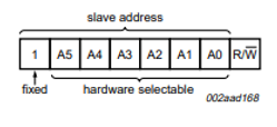
See page 7 of the PCA9685 data sheet for details.
- TSL2581

See page 13 of the TSL2581 data sheet for details.
Note: Our module default PCA9685 I2C address pins A5=A4=A3=A2=A1=A0=0, PCA9685's I2C address is 0x40, TSL2581's I2C address pins float (Float), TSL2581's I2C address is 0x39. If the user does not use the Raspberry Pi driver, for example, when using STM32 If the user does not use the Raspberry Pi driver, such as using STM32, the R/W bit needs to be added to the low bit.
Working with Raspberry Pi
Do not assemble the rudder first, because the initial angle of the rudder is not in the starting position, if the direct group turns up the rudder rotation may be stuck. It is recommended to test the angle of the rudder rotation separately first to prevent accidental damage to the rudder. Please follow the following tutorial in order to perform.
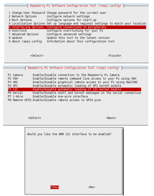
Enable I2C Interface
Open a terminal and run the following commands:
sudo raspi-config
Choose Interfacing Options -> I2C -> Yes.
Reboot Raspberry Pi:
sudo reboot
Install Library
If you use bookworm system, only the lgpio library is available, bcm2835 and wiringPi libarary cannot be installed or used. Please note that the python library does not need to install, you can directly run the demo.
BCM2835
#Open the Raspberry Pi terminal and run the following command
wget http://www.airspayce.com/mikem/bcm2835/bcm2835-1.71.tar.gz
tar zxvf bcm2835-1.71.tar.gz
cd bcm2835-1.71/
sudo ./configure && sudo make && sudo make check && sudo make install
# For more, you can refer to the official website at: http://www.airspayce.com/mikem/bcm2835/
WiringPi
#Open the Raspberry Pi terminal and run the following command
cd
sudo apt-get install wiringpi
#For Raspberry Pi systems after May 2019 (earlier than that can be executed without), an upgrade may be required:
wget https://project-downloads.drogon.net/wiringpi-latest.deb
sudo dpkg -i wiringpi-latest.deb
gpio -v
# Run gpio -v and version 2.52 will appear, if it doesn't it means there was an installation error

# Bullseye branch system using the following command:
git clone https://github.com/WiringPi/WiringPi
cd WiringPi
. /build
gpio -v
# Run gpio -v and version 2.70 will appear, if it doesn't it means there was an installation error
lgpio
wget https://github.com/joan2937/lg/archive/master.zip
unzip master.zip
cd lg-master
sudo make install
#for more details, you can refer to https://github.com/gpiozero/lg
Download the Demo
sudo apt-get install p7zip-full
wget https://files.waveshare.com/upload/9/96/Pan-Tilt_HAT_code.7z
7z x Pan-Tilt_HAT_code.7z -r -o./Pan-Tilt_HAT_code
sudo chmod 777 -R  Pan-Tilt_HAT_code
cd Pan-Tilt_HAT_code/RaspberryPi/
Debug
- How to connect:
| Brown | GND |
| Red | 5V |
| Orange | S1/S0 |
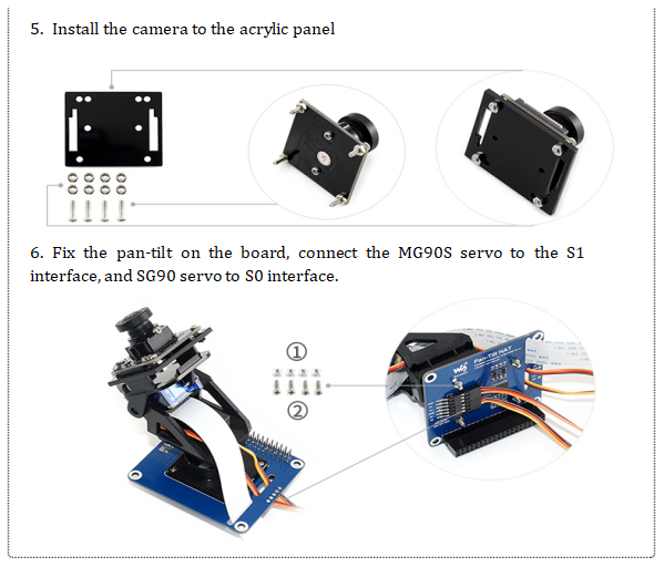
Before running the test code must pay attention to the installation position of the tilt servo, the installation position is not good and may lead to heat burned servo, first do not assemble the servo, to ensure that the servo can rotate 360 will not have obstacles, connect the hardware, pan servo connected to S1, tilt servo connected to S0. Then open the test folder in the program folder.
cd test
make clean
make
sudo ./main
After running, the servos all rotate to 0 degrees (the servo rotation angle is 0 to 180, that is, rotate to the initial position), then cut off the power assembly, take care not to rotate the tilt servo
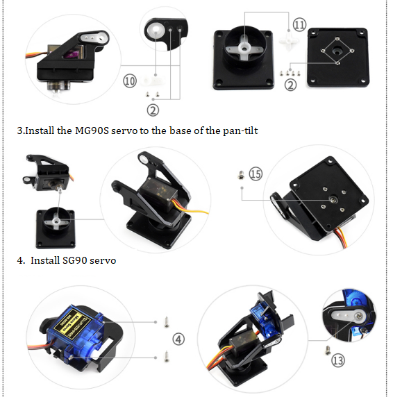
How to Assembe
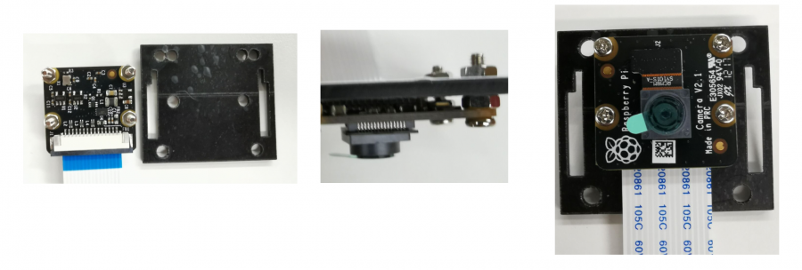
- Take RPi-Camera-I as the example, and other cameras may have some differences.
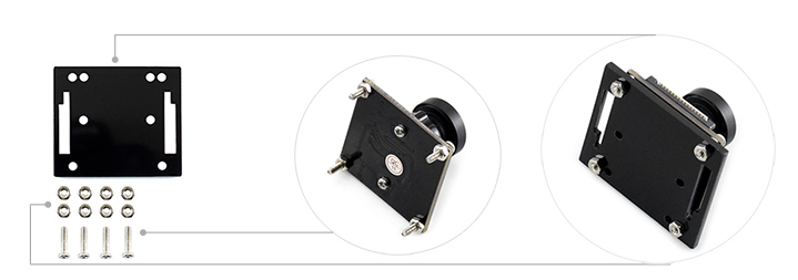
How to Connect Other Cameras
Module accessories provide a pack of M2 independent screw packages, a total of 5 screws and 10 nuts, the camera is all first to the camera on the M2 screws, lift the camera and then connect the acrylic plate, and the acrylic plate using screws to lock.
- RPi Camera V2
- RPi Camera (E)、RPi Camera (G)、RPi Camera (F)、RPi Camera (J)、RPi Camera (M)
- RPi Camera (H)
- RPi NoIR Camera V2
RPi IR-CUT Camera (as this camera hole is non-standard, so only two can be locked on)
Demo
#Execute the following under the Pan-Tilt-HAT/RaspberryPi/ directory:
#If you are using ambient light, execute this
cd Light_Sensor/
#If you are using a pan-tilt, execute this:
cd Servo_Driver/
- BCM2835
cd bcm2835
make clean
make
sudo ./main
- wiringpi
cd wiringpi
make clean
make
sudo ./main
- python
cd python
sudo python main.py
MJPG-STREAMER Real-time Monitor
- "MJPG-streamer", is used to capture images from the webcam and transfer them as a stream to the browser over an ip-based network.
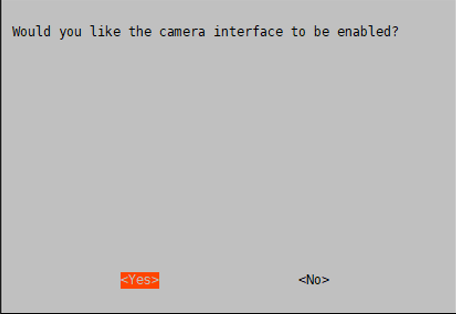
- Before using the webcam you must run the raspi-config command to enable the webcam:
sudo raspi-config
Select Enable Camera, select YES
- If the camera is using the CSI interface, then the system cannot find the device node /dev/video0. A line bcm2835-v4l2 needs to be added to the /etc/modules file:
sudo nano /etc/modules
Add:
bcm2835-v4l2

Then after the system boots, the system will load the module names in this file and reboot the system: sudo reboot
sudo reboot
ls /dev/video*
The video0 device node is found below.
![]()
- Run the following commands:
sudo apt-get update
sudo apt-get install libjpeg8-dev cmake
cd Pan-Tilt-HAT/RaspberryPi/web_Python
git clone https://github.com/jacksonliam/mjpg-streamer
cd mjpg-streamer/mjpg-streamer-experimental/
sudo make clean all
sudo ./start.sh
In Google Chrome (other browsers may not display) enter the Raspberry Pi IP address in the address bar, port number 8080, click Stream and it will show you what the camera is capturing in real-time.
If you need to know more you can check: https://github.com/jacksonliam/mjpg-streamer.

Remote Control via BOTTLE
Bottle is a simple and efficient follow WSGI mini python web framework. Bottle can be quickly implemented through web control, only python2 support.
Installed libraries:
sudo apt-get install python-bottle
cd Pan-Tilt-HAT/RaspberryPi/web_Python/
sudo python main.py
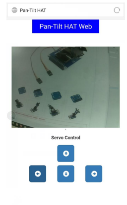
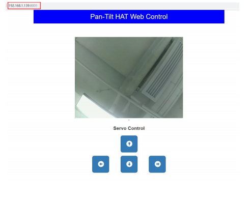
Enter the Raspberry Pi IP address and port number 8001 in the address bar of Google Chrome (other browsers may be abnormal), the following page will be displayed, click the button to remote control.

Support cell phone and computer control, no APP required.
Cell phone control:
Control with PC:
Jetson Nano
Install Library
Install Function Library
- Open the terminal interface and input the following function library:
sudo apt-get update
sudo apt-get install python3-pip
sudo pip3 install Jetson.GPIO
sudo groupadd -f -r gpio
sudo usermod -a -G gpio your_user_name
sudo cp /opt/nvidia/jetson-gpio/etc/99-gpio.rules /etc/udev/rules.d/
sudo udevadm control --reload-rules && sudo udevadm trigger
- Install I2C:
sudo apt-get install python-smbus
- Install image process library:
sudo apt-get install python3-pil
sudo apt-get install python3-numpy
Demo Download
sudo apt-get install p7zip
wget https://files.waveshare.com/upload/9/96/Pan-Tilt_HAT_code.7z
7zr x Pan-Tilt_HAT_code.7z -r -o./Pan-Tilt_HAT_code
sudo chmod 777 -R  Pan-Tilt_HAT_code
cd Pan-Tilt_HAT_code/JetsonNano/
Of course, you can also download the project on our Github page: udo git clone
sudo git clone https://github.com/waveshare/Pan-Tilt-HAT
cd Pan-Tilt-HAT/JetsonNano/
Demo
# If using ambient light, run this
cd 1_Light_Sensor/
#If using a pan-tilt, run this
cd 2_Servo_Driver/
- python
#python2
cd python2
sudo python main.py
#python3
cd python3
sudo python3 main.py
Cell Phone Control Camera
Camera Test
DISPLAY=:0.0 gst-launch-1.0 nvarguscamerasrc ! \'video/x-raw(memory:NVMM), width=1920, height=1080, format=(string)NV12, framerate=(fraction)30/1\' ! nvoverlaysink -e
The data captured by the normal camera will be displayed on the screen. Press Ctrl + c to end.
APP Download
Download the Android phone APP: AlphaBot
Pan-tilt Control
Run in the terminal:
cd 3_Pan-Tilt+CAM
sudo python main.py
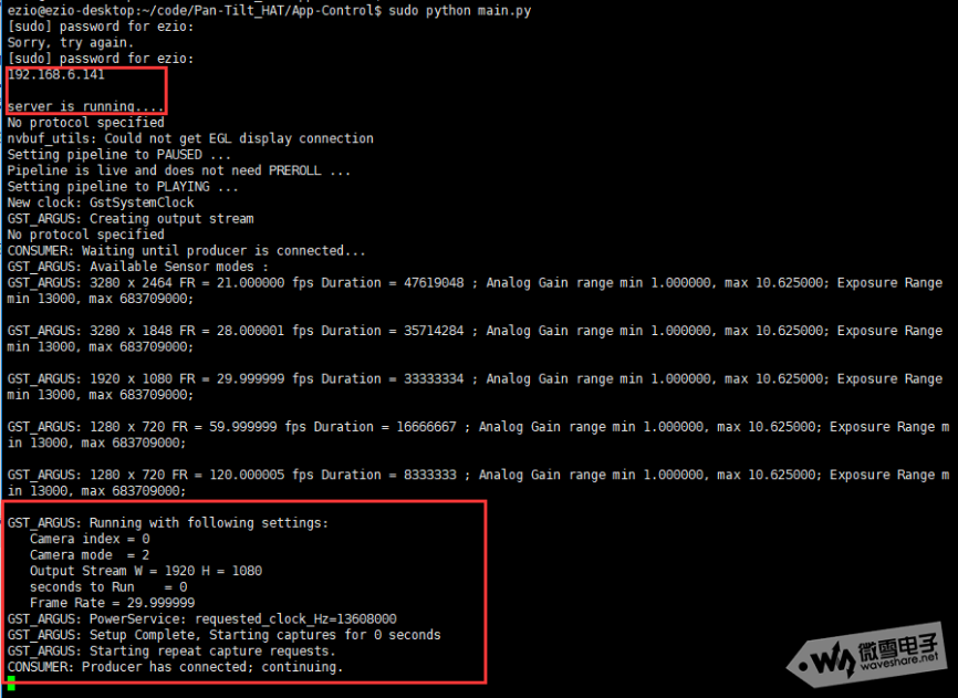
The first one will get the IP address of Jetson, which will be used later in the app.
The latter is the camera is working, and displayed on the screen.
Cell phone APP control, open the App, click Wifi control:
Enter the IP address: 192.168.6.14
Enter the control interface, only the four keys on the right can be used.
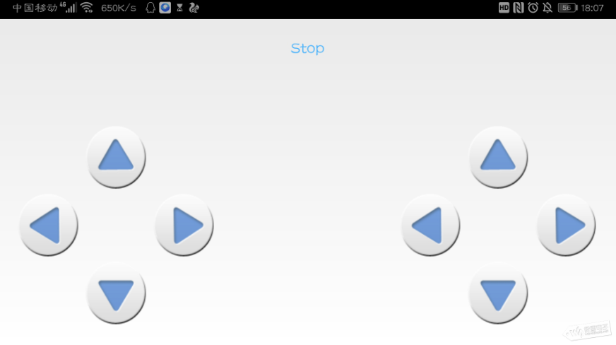
Rotate the camera and the screen displays the camera data in real-time:

Resources
Datasheet
FAQ
{{{5}}}
{{{5}}}
{{{5}}}
- Detect whether the servo line is connected to the wrong
- Exchange the wiring interface of the two servos to see if the problem is the servo or if there is no output from one interface.
- Remove the other accessories first to test whether the servo is rotating.
- If you have another Raspberry Pi, you can replace the other Raspberry Pi to test, it may be a problem with the Raspberry Pi pins.
- It may be because of the configuration in the system, you may test it with a new Raspberry Pi system again.
{{{5}}}
Support
Technical Support
If you need technical support or have any feedback/review, please click the Submit Now button to submit a ticket, Our support team will check and reply to you within 1 to 2 working days. Please be patient as we make every effort to help you to resolve the issue.
Working Time: 9 AM - 6 PM GMT+8 (Monday to Friday)

