
DCGM-N20-12V-EN-200RPM
| ||

Introduction
This product is a high-precision N20 DC gear motor with a magnetic Hall encoder, all-metal gear, and an L-shaped 6PIN connector. It is suitable for application scenarios such as intelligent robots, smart homes, etc.
Features
- 7-wire Hall encoder.
- All-metal gear & high-precision reduction motor.
- Up to 200rpm non-load speed.
- Locked-rotor torque: 1.2kg.cm
- Screw terminal: ZH1.5-6PIN
Parameters
| Rated Voltage |
DC 12V |
|---|---|
| No-load Speed | 200rpm |
| No-load Current | 0.1A MAX |
| No-load Startup Voltage | 3.0V MAX |
| Locked-rotor Torque | ≥1.2 kg.cm |
| Locked-rotor Current | ≤1.1A |
| Hall Resolution | Basic 7PPR×150=1050PPR |
| Gear Reduction Ratio | 1:150 |
Working Mode

Running Demo
Install Arduino IDE
-
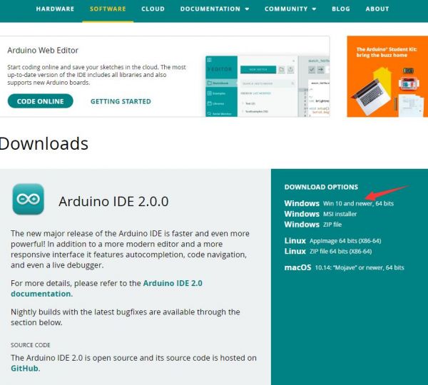
Download Arduino IDE:
Download the latest Arduino IDE 2.1.0 package from Arduino website. The official IDE supports different operating systems, you can install it according to your operating system. Here, the package downloaded is the Windows version (If you have installed it, you can skip to step 2). The installation process is easy, just keep clicking on "Next".
-
Click to install after downloading.
 Note: You will be prompted to install the driver during the installation process, just click Install.


Install ESP32 Plug-in In Arduino IDE
-
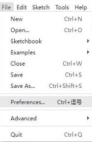
Open Arduino IDE, click the File on the left corner, and choose "Preferences".
-
Add the following link in the additional boards manager URLs, then click OK.
https://dl.espressif.com/dl/package_esp32_index.json
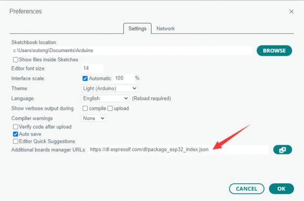
Note: If you need to add multiple development board URLs, there is no need to delete the URLs supported by the ESP32 development board. You can directly add other URLs to another line, with each URL separated by commas.
For example, if you need to add URLs for the ESP8266 development board, simply add them to another line. The display will appear as follows:https://dl.espressif.com/dl/package_esp32_index.json,http://arduino.esp8266.com/stable/package_esp8266com_index.json
-
Download the package, and copy the unzipped package files to the following path:
C:\Users\username\AppData\Local\Arduino15
Username changes according to your own computer's username, copy the unzipped packages file to the Arduino15 folder.


Install Dependency Library
- Click on the third icon on the left for the library manager, type "INA219_WE" in the search field, find the dependency library INA219_WE, and click on install.

- Then type "Adafruit_SSD1306" in the search bar to find the dependency library Adafruit_SSD1306 and click Install.

- Download and unzip the dependency library ESP32Servo, open the default installation location of Arduino: C:\Users\username\AppData\Local\Arduino15\libraries, username changes according to your own computer's username, and then copy the folder in the picture to the Libraries folder.

Upload Demo
-
Download demo and double-click speedLoopCtrl.ino.
-
Click Tools -> Port, remember the existing COM, and do not click this COM. (There are different COM ports in different computers, and you need to remember the existing COM in your computer.)
-
Connect the multifunction driver board to the computer using a USB cable (plug the USB Type-C interface of the multifunction driver board here). Click on "Tools" → "Port", then click on the newly appeared COM.
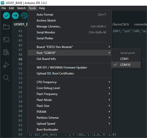
-
Click Tools -> Board -> esp32 -> ESP32 Dev Module.

-
After setting, you can click Upload to upload the demo to your device.
- After uploading the program, connect the N20 motor to the motor PH2.0 2P connector on the general driver for robots, and connect the XH2.54 power supply connector on the driver board to the power supply, and then you can see that the motor starts to rotate quickly.


- If you encounter problems during the upload period and need to reinstall or change the Arduino IDE version, you need to uninstall the Arduino IDE clean. After uninstalling the software, you need to manually delete all the contents of the folder C:\Users\username\AppData\Local\Arduino15 (Some hidden files need to be displayed to be seen) and then reinstall.
Demo Analysis
// --- --- --- Encoder demo --- --- ---

// Encoder A pinout definition
const uint16_t AENCA = 35;        // Encoder A input A_C2(B)
const uint16_t AENCB = 34;        // Encoder A input A_C1(A)

// Encoder B pinout definition
const uint16_t BENCB = 16;        // Encoder B input B_C2(B)
const uint16_t BENCA = 27;        // Encoder B input B_C1(A)

// Calculate the number of high-low level transitions of a Hall sensor of the encoder within a specified "interval" time (in milliseconds)
// Because the interrupt initialization later uses RISING, specifically, it refers to the number of transitions from low to high level
volatile long B_wheel_pulse_count = 0;
volatile long A_wheel_pulse_count  = 0;

// Calculate the period time for speed, meaning that the speed is calculated for every specified number of milliseconds
int interval = 100;

// The current time
long currentMillis = 0;

// The reduction ratio of the motor, the motor speed and the output shaft speed of the motor are different
// For example, the DCGM3865 motor has a reduction ratio of 1:42, which means the motor must rotate 42 times for the output shaft to rotate once.
// For one rotation of the output shaft, the motor needs to rotate more revolutions. Typically, a higher reduction ratio results in greater torque.
// Take the DCGM3865 motor (reduction ratio 1:42) as an example:
double reduction_ratio = 150;

// The encoder line count refers to the number of changes in the high-to-low or low-to-high signal transitions of a Hall sensor of the encoder for one rotation of the motor.
int ppr_num = 7;

// Number of high-low level changes in one Hall sensor of the encoder for one revolution of the output shaft
double shaft_ppr = reduction_ratio * ppr_num;

// The callback function of the interrupt function, refer to the attachInterrupt() function later
void IRAM_ATTR B_wheel_pulse() {
  if(digitalRead(BENCA)){
    B_wheel_pulse_count++;
  }
  else{
    B_wheel_pulse_count--;
  }
}

void IRAM_ATTR A_wheel_pulse() {
  if(digitalRead(AENCA)){
    A_wheel_pulse_count++;
  }
  else{
    A_wheel_pulse_count--;
  }
}
// --- --- --- --- --- --- --- --- ---

// --- --- --- Motor Control --- --- ---
// The following code defines the ESP32 pin for controlling TB6612
// Motor A
const uint16_t PWMA = 25;         // Motor A PWM control  Orange
const uint16_t AIN2 = 17;         // Motor A input 2      Brown
const uint16_t AIN1 = 21;         // Motor A input 1      Green

// Motor B
const uint16_t BIN1 = 22;        // Motor B input 1       Yellow
const uint16_t BIN2 = 23;        // Motor B input 2       Purple
const uint16_t PWMB = 26;        // Motor B PWM control   White

// The PWM frequency for the PWM output pin
int freq = 100000;

// Defines PWM channel
int channel_A = 5;
int channel_B = 6;

// Defines PWM accuracy, when it is 8, the PWM value is 0-255(2^8-1)
const uint16_t ANALOG_WRITE_BITS = 8;
// The max PWM value
const uint16_t MAX_PWM = pow(2, ANALOG_WRITE_BITS)-1;
// The minimum PWM value, as the low-speed characteristics of a DC motor are generally poor, and excessively low PWM values may not meet the motor's threshold for rotation
const uint16_t MIN_PWM = MAX_PWM/5;

// Motor A control
void channel_A_Ctrl(float pwmInputA){
  // Round the pwmInput value to the nearest integer
  int pwmIntA = round(pwmInputA);

  // If pwmInput=0, it stops rotating
  if(pwmIntA == 0){
    digitalWrite(AIN1, LOW);
    digitalWrite(AIN2, LOW);
    return;
  }

  // Determine the direction of rotation by determining the positive or negative pwmInput value
  if(pwmIntA > 0){
    digitalWrite(AIN1, LOW);
    digitalWrite(AIN2, HIGH);
    // constrain() function is for limiting the pwmIntA value between MIN_PWM and MAX_PWM
    ledcWrite(channel_A, constrain(pwmIntA, MIN_PWM, MAX_PWM));
  }
  else{
    digitalWrite(AIN1, HIGH);
    digitalWrite(AIN2, LOW);
    ledcWrite(channel_A,-constrain(pwmIntA, -MAX_PWM, 0));
  }
}

// Motor B control
void channel_B_Ctrl(float pwmInputB){
  int pwmIntB = round(pwmInputB);
  if(pwmIntB == 0){
    digitalWrite(BIN1, LOW);
    digitalWrite(BIN2, LOW);
    return;
  }

  if(pwmIntB > 0){
    digitalWrite(BIN1, LOW);
    digitalWrite(BIN2, HIGH);
    ledcWrite(channel_B, constrain(pwmIntB, 0, MAX_PWM));
  }
  else{
    digitalWrite(BIN1, HIGH);
    digitalWrite(BIN2, LOW);
    ledcWrite(channel_B,-constrain(pwmIntB, -MAX_PWM, 0));
  }
}
// --- --- --- --- --- --- --- --- ---

// --- --- --- Close-loop Control --- --- ---
// PID controller parameters
double Kp = 0.05;   // Proportionality factor
double Ki = 0.05;   // Integral coefficient
double Kd = 0;   // Differentiation factor

// Target speed and actual speed
double targetSpeed_A = 100.0;  // Target speed (configurable)
double actualSpeed_A = 0.0;   // Actual speed
double targetSpeed_B = 100.0;  // Target speed (configurable)
double actualSpeed_B = 0.0;   // Actual speed

// PID controller variables
double previousError_A = 0.0;
double integral_A = 0.0;
double previousError_B = 0.0;
double integral_B = 0.0;
// --- --- --- --- --- --- --- --- ---

void setup(){
  // Set the working mode for the related pins of the encoder
  pinMode(BENCB , INPUT_PULLUP);
  pinMode(BENCA , INPUT_PULLUP);

  pinMode(AENCB , INPUT_PULLUP);
  pinMode(AENCA , INPUT_PULLUP);

  // Set up an interrupt and its corresponding callback function, so that when BEBCB transitions from a low level to a high level (RISING), the function B_wheel_pulse is called
  attachInterrupt(digitalPinToInterrupt(BENCB), B_wheel_pulse, RISING);
  // Set up an interrupt and its corresponding callback function, so that when AEBCB transitions from a low level to a high level (RISING), the function A_wheel_pulse is called.
  attachInterrupt(digitalPinToInterrupt(AENCB), A_wheel_pulse, RISING);

  // Initialize the serial port, and the baud rate is 115200
  Serial.begin(115200);
  // Wait for the serial port initialization
  while(!Serial){}

  // Set up the working mode for ESP32 pins to control TB6612FNG
  pinMode(AIN1, OUTPUT);
  pinMode(AIN2, OUTPUT);
  pinMode(PWMA, OUTPUT);
  pinMode(BIN1, OUTPUT);
  pinMode(BIN2, OUTPUT);
  pinMode(PWMB, OUTPUT);

  // Setting the channel, frequency and accuracy of the ESP32 pin used for PWM outputs
  ledcSetup(channel_A, freq, ANALOG_WRITE_BITS);
  ledcAttachPin(PWMA, channel_A);

  ledcSetup(channel_B, freq, ANALOG_WRITE_BITS);
  ledcAttachPin(PWMB, channel_B);

  // The pin used to control rotation is placed at a low level, and the motor stops rotating to avoid starting rotation immediately after initialization
  digitalWrite(AIN1, LOW);
  digitalWrite(AIN2, LOW);
  digitalWrite(BIN1, LOW);
  digitalWrite(BIN2, LOW);
}

void loop(){
  // Calculate the speed of the output shaft of the motor B in revolutions per minute
  actualSpeed_B = (float)((B_wheel_pulse_count / shaft_ppr) * 60 * (1000 / interval));
  B_wheel_pulse_count = 0;

  // Calculate the speed of the output shaft of the motor A in revolutions per minute
  actualSpeed_A = (float)((A_wheel_pulse_count / shaft_ppr) * 60 * (1000 / interval));
  A_wheel_pulse_count = 0;

  // Calculate error and control volume
  double error_A = targetSpeed_A - actualSpeed_A;
  integral_A += error_A;
  double derivative_A = error_A - previousError_A;

  double error_B = targetSpeed_B - actualSpeed_B;
  integral_B += error_B;
  double derivative_B = error_B - previousError_B;

  // Calculate PID output
  double output_A = Kp * error_A + Ki * integral_A + Kd * derivative_A;
  double output_B = Kp * error_B + Ki * integral_B + Kd * derivative_B;

  // output_A += Kp * error_A;
  // output_B += Kp * error_B;

  // Limits the output range
  output_A = constrain(output_A, -MAX_PWM, MAX_PWM);
  output_B = constrain(output_B, -MAX_PWM, MAX_PWM);

  // Output PWM signal to control the motor speed
  channel_A_Ctrl(-output_A);
  channel_B_Ctrl(-output_B);

  // Update the last error value
  previousError_A = error_A;
  previousError_B = error_B;

  Serial.print("RPM_A: ");Serial.print(actualSpeed_A);Serial.print("   RPM_B: ");Serial.println(actualSpeed_B);
  Serial.println("--- --- ---");

  delay(interval);
}
Resource
3D Model
2D Drawing
Support
Technical Support
If you need technical support or have any feedback/review, please click the Submit Now button to submit a ticket, Our support team will check and reply to you within 1 to 2 working days. Please be patient as we make every effort to help you to resolve the issue.
Working Time: 9 AM - 6 PM GMT+8 (Monday to Friday)