Core51822 (B)
| ||
Introduction
BLE4.0 Bluetooth 2.4G Wireless Module, nRF51822 Onboard
| More |
- Core51822 is a wireless module based on nRF51822 - the Multiprotocol Bluetooth® 4.0 low energy/2.4 GHz RF SoC designed for ULP (ultra-low power) wireless applications.
- Core51822 (B) is a wireless module based on nRF51822 - the Multiprotocol Bluetooth® 4.0 low energy/2.4 GHz RF SoC designed for ULP (ultra-low power) wireless applications.
- BLE400 is a mother board designed for BLE4.0 Bluetooth 2.4G Wireless Module.
- NRF51822 Eval Kit is a development/evaluation kit designed for nRF51822, consists of the mother board BLE400 and the wireless module Core51822.
BLE400 Features
- Onboard battery holder, multi-power supplies are available.
- All the IOs are accessible for easy expansion.
- Integrates CP2102 for debugging.
- LEDs and user keys, compatible with other official boards, easy to use.
Out of box audit
PC development environment deployments
- WindowsXP or Windows 7
- nRFgo Studio v1.14 or higher versions
- Keil MDK-ARM Lite v4.54 or higher versions
- J-Link Software v4.52b or higher versions
Mobile app download
For iOS: enter App Store and search nRF Utility
For Android (4.3 or later): download nRFToolbox then unzip and install it.
Notice: The development method of Bluetooth 4.0 is different from the traditional one. So your phone can find Bluetooth 4.0 signal only if it supported Bluetooth 4.0 and installed a related App.
How to connect with a mobile phone (Bluetooth to serial demo)
a) Install the CP2102 Driver.
b) Connect the mini USB Port of BLE400 to your PC.
c) Choose and check a corresponding Serial Port which was set as Baud rate -> 38400, Data bit -> 8, Stop bit -> 1.
d) Send a character Y or y and then if the word Start... is received, means that your Bluetooth device is broadcasting. At this time, the LED0 on BLE400 lights up.
Note: The first part of the factory program is for self-test, so the information displayed can be ignored.
e) Open the Bluetooth function on your phone.
f) Open nRFToolbox and enter UART then click the button CONNECT. Select "Nordic_UART" on the list and at this time LED0 off and LED1 on, which means that your phone is successfully connected to the module.
g) Tap the button on the App and some characters will be received by Serial.
h) Click Show Log and send a string, e.g. abcdefghijklmnopqrs, by Serial from PC, then the corresponding information will be displayed on the LOG list.
Note: the App displays received data only if 19 characters are received.
Program descriptions
SDK
- Install Keil MDK-ARM (v4.54 or higher version) and J-Link for Windows.
- Save nRF51 SDK and open the nrf51_sdk_v5_2_0_xxxxx.msi file to install. Please ensure the KeilMDK-ARM option is selected.
- It is noticed that if there are installation errors of SDK, please download and install Microsoft .NET Framework 3.5.
- Install nRFgo Studio (nRFgo Studio win32 for a 32-bit system, and nRFgo Studio win64 for a 64-bit system).
Example application programming explanations
There are a few differences in programming different example applications. In the following two sections, we will take blink_example and ble_app_hrs as two examples to illustrate how to program example applications.
Here are the main differences in programming blink_example and ble_app_hrs applications.
- The blinky_example is like an application run without OS. So it can be applied directly after Programming Application.
- The ble_app_hrs is like an application that should be run in an OS. Therefore, both relative firmware and its codes should be downloaded.
How to compile and program blinky_example
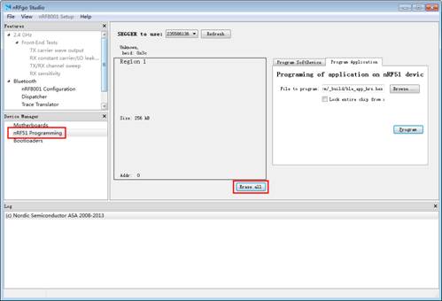
- Before programming, you should apply nRFgo Studio to erase all the programs preinstalled to the development board by the manufactory. The erasure can be easily done by selecting nRF51 Programming and clicking Erase all. Now, it is ready to program the applications.

|
- Open Blinky Project in Keil μVision under the path of <KEIL path> \ARM\Device\Nordic\nRF51822\Board\PCA10001\blinky_example\arm\blinky.uvproj or ...\code\BLE4.0\nrf51822\Board\pca10001\blinky_example\arm\blinky.uvproj
- Click the icon Build or press the fast key, F7, to compile Blinkly project.
- Click the icon Download. Run the Blinky_example after the program download is finished. Then, you can see the LED start to flick.

|
Notice:
Sometimes, Jlink firmware may fail to cooperate with Nordic SDK, causing KEIL cannot download demos.
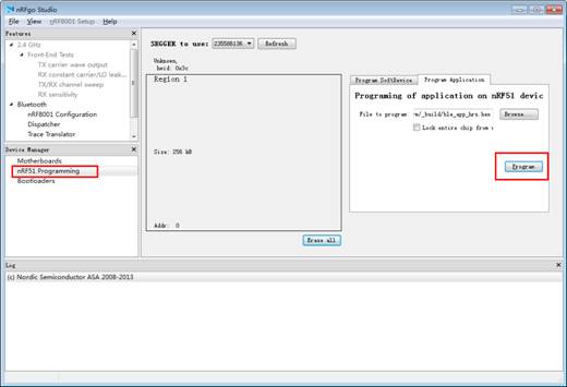
In this case, please select nRF51 Programming at the bottom left of nRFgo Studio, and click the option Program Application to start programming.

|
How to compile and program ble_app_hrs
- Program S110 nRF51822 SoftDevice (Bluetooth protocol stack):
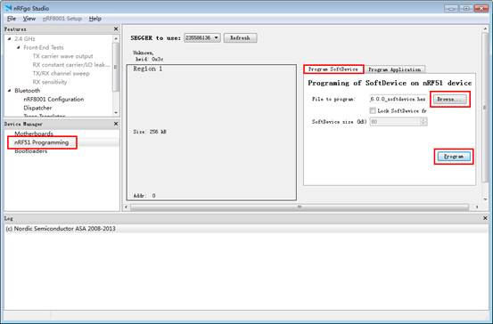
Select nRF51 Programming > Program SoftDevice> Browse (choose corresponding Bluetooth protocol stack) > Program (wait for completing Bluetooth protocol stack programming).
Notes: The protocol stack file we used here, s110_nrf51822_6.0.0_softdevice.hex, is decompressed from \Software\s110_nrf51822_6.0.0.zip.

|
- Enter <KEIL path> \ARM\Device\Nordic\nrf51822\Board\pca10001\s110\ble_app_hrs\arm or <code path>\BLE4.0\nrf51822\Board\pca10001\s110\ble_app_hrs\arm. And then, open Keil project file.
- Follow the steps mentioned above to compile and download.
Functional descriptions of example programs
- All the programs are under the path of <code path>\BLE4.0\nrf51822\Board\pca10001 and all the jumpers are connected.
- For the detailed explanations of processes ①, ②, ③, and ④ in the table below, please refer to the remarks at the bottom of the table.
- For the operations involving process ②, please refer to the section "How to compile and program ble_app_hrs" to find out the relative program method.
- For other demos, please refer to the section “How to compile and program blinky_example” to find out the relative program method.
| Program name | Operations and phenomenon |
| blinky_example | LED is flickering |
| uart_example | ①, and read back serial output information |
| at45dbxx_example | ①, and connect AT45DBXX DataFlash Board to a SPI
The ID of the module will be shown in the serial debugging assistant. |
| at24cxx_example | ①, and connect AT24CXX EEPROM Board to an I2C interface
Press KEY1 on the development board, and then the data of the assigned address will be shown in the serial debugging assistant. Press KEY2 on the development board, and then the data of the assigned address will be increased by 1. |
| button_radio_example\led_radio_example | Development board A downloads button_radio_example
Development board B downloads led_radio_example Press KEY1 on the development board A, and then LED0 starts flickering Press KEY2 on the development board B, and then LED1 starts flickering |
| ble_app_beacon | ②, ③, ④ |
| ble_app_proximity | ②, ③, ④ |
| ble_app_uart | ①, ②, ③, ④, and transmit the data in the mobile phone to a serial port |
Remarks:
① Connect the development board to a PC via a data cable, and start the serial debugging assistant; Baud rate: 38400, 8-bit data bit, 1-bit stop bit.
② Download the Blue tooth protocol stack from Program SoftDevice.
③ Testing software: LightBlue(iOS).
④ LightBlue displays relative information.
Resources
NRF51822 Software
- nRFToolbox
- CP2102 Driver
- Jlink Driver
- nRF51 SDK
- nRFgo Studio win32
- nRFgo Studio win64
- s110-nrf51822 Protocol stack
- s110-nrf51822 Protocol stack
NRF51822 Design Resources
- NRF51-Reference-manual
- NRF51-Series-Reference-Manual
- S120-SoftDevice-Specification
- S110-SoftDevice-Specification
- NRF51822-PS
- PAN-028
- PCN-083-nRF51x22-deviation-tuning
- PCN-085
- PCN-086-Plastic-Reel-Change
Other Board
Support
Technical Support
If you need technical support or have any feedback/review, please click the Submit Now button to submit a ticket, Our support team will check and reply to you within 1 to 2 working days. Please be patient as we make every effort to help you to resolve the issue.
Working Time: 9 AM - 6 PM GMT+8 (Monday to Friday)


