Compute-Module-4
| ||
| ||
| ||
Overview
Introduction
I am the 4th generation IO board of the Raspberry Pi Compute Module. The Compute Module 4 IO Board is a baseboard officially released by the Raspberry Pi that can be used with the Raspberry Pi Compute Module 4. It can be used as the development system of the Compute Module 4 and as Embedded boards are integrated into end products, or systems can be created quickly using off-the-shelf components such as Raspberry Pi HAT and PCIe modules. Its interface is concentrated on the same side, which is convenient for users to use.
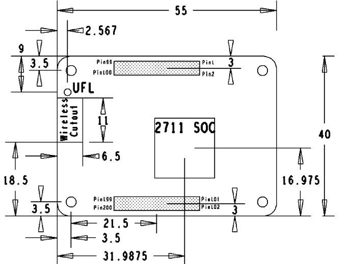
Product dimension
For more description, please visit: module 4_IO board
Notes
Do not plug or unplug any device while it is powered on.
Writing Image
- Write Image for Compute Module Boards eMMC version
- Write Image for Compute Module Boards Lite version
USB2.0
The USB port is disabled by default on the CM4 to save power. If you need to start, you need to add the following to the config.txt file:
dtoverlay=dwc2,dr_mode=host
After restarting:
If you use the latest Raspberry Pi OS (image after October 30, 2021) USB2.0 is OTG mode by default, CM4 will report an error:
config failed, hub doesn't have any ports! (err -19)
However, USB can still be used. If you want to remove this error, remove otg_mode=1 in [cm4] of config.txt, and add dtoverlay=dwc2, dr_mode=host (USB cannot be recognized without adding it).

PCIe Gen 2 x 1
PCle sockets are designed to accept standard PC PCle cards. You should make sure you have an OS driver for your card.
The PCle link has been successfully used with NVMe drives via a passive PCle adapter.
Note: PCle interface does not support MSI-X. Typical PCle devices will fall back to MSI.
RTC FAN
This extended version only supports 12V.
- Note: Please connect the fan before turning on the power of the baseboard and then complete the test. Please do not connect the fan after the baseboard is powered on, because the fan control chip has been powered on, otherwise, the chip will be burned!
- Note: Before connecting, please confirm whether the rated voltage of the fan is consistent with the voltage connected to the fan.
Please note that DSI and CSI are prohibited when using RTC.
I2C-10 is used by default.
RTC (PCF85063a) on i2c-10, address is 0 x 51 (7-bit address)
FAN (EMC2301) on i2c-10, address is 0 x 2f (7-bit address)
If you need to add it to your program instead of the kernel, you can refer to the C and Python demo reference click here.
RTC
sudo nano /boot/config.txt
 #Add the following lines at the end
 dtparam=i2c_vc=on
 dtoverlay=i2c-rtc,pcf85063a,i2c_csi_dsi
 #Add # in front of dtparam=audio=on
 #dtparam=audio=on
 #Save and exit, restart
 sudo reboot
How to use Hwclock
Synchronize system clock to hardware clock:
sudo hwclock -w
Synchronize hardware clock to system clock:
sudo hwclock -s
 #The network or the NTP needs to be closed, otherwise it will be changed back.
Set the hardware clock time:
sudo hwclock --set --date="9/8/2021 16:45:05"
View hardware clock:
sudo hwclock -r
Display version information:
sudo hwclock --verbose
Fan
1: Check if the kernel version is higher than or equal to 6.1.31.
uname --all
2: Add the following content at config.txt:
dtoverlay=i2c-fan,emc2301,i2c_csi_dsi,midtemp=45000,maxtemp=65000
3: For more parameters, you can refer to this link
Troubleshooting
1: After configuration, you can use the command "i2cdetect -y 10" to check whether the configuration is valid, and the valid I2C address should be UU without digits.
2: RTC value is not accurate, or an invalid prompt appears, check whether the RTC battery is connected and whether the voltage of the RTC battery is normal.
3: All configurations need to be rebooted after being added to take effect.
4: If the fan does not rotate after adding the fan driver, you can press "1" to troubleshoot and check whether the configuration is effective. If it is valid, then you can check whether the kernel version is higher or equal to 6.1.31 (uname --all). If the version is lower than 6.1.31, this kernel cannot work. For more details, you can refer to this link.
CSI DSI
Configuration file
CSI and DSI are disabled by default. When using the camera and DSI, it will occupy three I2C devices: I2C-10, I2C-11, and I2C-0.
- Open a terminal and run the following commands:
sudo apt-get install p7zip-full -y
wget https://files.waveshare.com/upload/7/75/CM4_dt_blob.7z
7z x CM4_dt_blob.7z -O./CM4_dt_blob
sudo chmod 777 -R CM4_dt_blob
cd CM4_dt_blob/
# If using two cameras and DSI1, please execute:
sudo dtc -I dts -O dtb -o /boot/dt-blob.bin dt-blob-disp1-double_cam.dts
# When using any DSI, there is no image output on HDMI1. Even if you do not connect a DSI screen, as long as the corresponding file is compiled, there will be no output on HDMI1.
# To restore it, simply delete the corresponding dt-blob.bin file: sudo rm -rf /boot/dt-blob.bin
#Execution is complete, power off and reboot CM4
New Version (Bullseye)
Camera Config
-
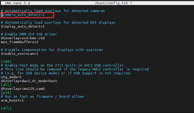
Execute the following commands to edit "/boot/config.txt" file.
sudo nano /boot/config.txt
- Block or remove the automatic camera detection statement:
-
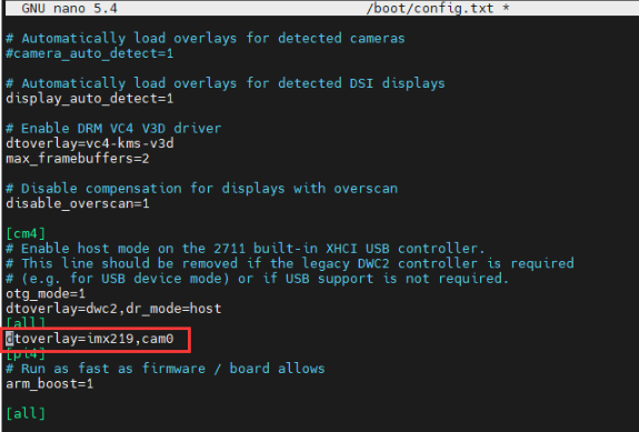
Add the driver of the camera you are using, here I take IMX219 as an example and connect it to CAM0, and attach the adapter.
Model CAM0 Set Sentence CAM1 Set Sentence OV9281 dtoverlay=ov9281,cam0 dtoverlay=ov9281,cam1 IMX290/IMX327 dtoverlay=imx290,clock-frequency=37125000,cam0 dtoverlay=imx290,clock-frequency=37125000,cam1 IMX378 dtoverlay=imx378,cam0 dtoverlay=imx378,cam1 IMX219 dtoverlay=imx219,cam0 dtoverlay=imx219,cam1 IMX477 dtoverlay=imx477,cam0 dtoverlay=imx477,cam1 IMX708 dtoverlay=imx708,cam0 dtoverlay=imx708,cam1 - If you are using the official Raspberry Pi camera and only one camera is connected, there is no need to set the config file. If it is not an official camera, set the "dtoverlay" statement without the "cam" suffix.
- CM4-NANO - only CAM0 is used, so you only need to add "dtoverlay=imx219,cam0".
5. Ctrl+x to exit the editor.
6. Reboot the Raspberry Pi.
sudo reboot
Camera Test
- Enter the camera detection command, you can see that the camera is detected by now.
libcamera-hello --list-cameras
- Display the camera screen on the desktop.
- Taking photos.
libcamera-jpeg -o test.jpg
- Record a video of 10s.
libcamera-vid -t 10000 -o test.h264
Other Commands:
libcamera-hello -t
Check whether the camera is detected:
libcamera-hello --list-cameras
Open the corresponding cameras:
libcamera-hello  --camera 1
libcamera-hello  --camera 0
Take a photo:
libcamera-jpeg -o test.jpg
#Add --camera to specify a camera
Old Version (Buster)
Camera Config
-
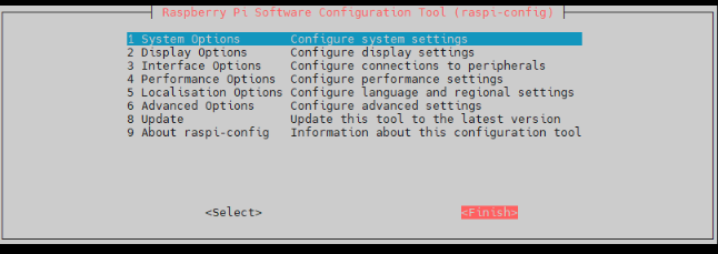
1. Execute the following command to enter the Raspberry Pi configuration.
- Test the recording function:
- Where -t 10000 means recording for 10 seconds, users can adjust according to their own needs.
- Please refer to CSI.
sudo raspi-config
2. Choose Interfacing Options and enter.

3. Choose Camera:

4. Choose to enable the camera interface.

5. The system prompts as follows:

6. Back to the main interface, select Finish.

7. Reboot the system.

Camera Test
raspistill -o image.jpg
raspivid -o video.h264 -t 10000
Resource
Official Manual
- Compute Module IO Board Datasheet
- Raspberry Pi Compute Module 4 IO Board Product Brief
- Raspberry Pi Compute Module 4 IO Board Datasheet
Program
Sample demo (Unofficial Example):
FAQ
b) Check whether the /boot/dt-blob.bin file exists, if it cannot be used, delete it.
At present, CAM1 is the default in use. If you want to use CAM0, you'll need to follow the instructions in the configuration file to set up the camera for CAM0. If you want to use both interfaces simultaneously, you'll need to configure it using the dual-camera method.
{{{5}}}
It can be powered by 5V and GND of 40PIN or micro USB cable.
{{{5}}}
Support
Technical Support
If you need technical support or have any feedback/review, please click the Submit Now button to submit a ticket, Our support team will check and reply to you within 1 to 2 working days. Please be patient as we make every effort to help you to resolve the issue.
Working Time: 9 AM - 6 PM GMT+8 (Monday to Friday)


