AlphaBot2-old
New version wiki: https://www.waveshare.com/wiki/AlphaBot2
Overview
Introduction
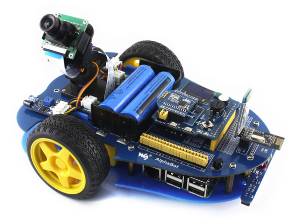
AlphaBot2 robot building kit for Arduino/Pi/PiZero
| More |
Functions
As Arduino and Raspberry Pi are the popular development board recently, intelligent robot cars are also a favorite project of many electronics enthusiasts, and AlphaBot is a good choice.
Just connecting a controller board, Raspberry Pi or Arduino, and combined with our open-source example code, AlphaBot is ready to start exploration: line tracking, obstacle avoidance, video monitoring, WiFi/Bluetooth/ZigBee/Infrared remote control, etc.
AlphaBot can perceive its environment and perform relative responses. It involves
the following technologies: Tracking line, obstacle avoidance, mobile phone/PC video monitoring, WIFI/Bluetooth/ZigBee/infrared remote control, and the likes.
Notes: This document is not for any specific product kits. Some of them may not have the component(s) described in the sections below. For more information about the product kit, please refer to the product page on the Waveshare website.
Features
- Raspberry Pi/Arduino interfaces, work with either one separately, or both.
- Arduino extended header, supports Arduino shields.
- Modular design, plug-and-play modules like line tracking, obstacle avoidance, speed measuring, etc. eliminating the trouble of connecting mess wires.
- L298P motor driver with diode protection circuit, more safety.
- LM2596 voltage regular provides stable 5V power to the Raspberry Pi/Arduino.
- TLC1543 AD acquisition chip, allows the Pi to use analog sensors.
Recommandation
Reading this document can be a challenge for a freshman. We advise that the reader needs to have some knowledge of programming in Raspberry Pi Python
or Arduino, which can be helpful for understanding the programming fundamentals.
Due to space constraints, only a few of the programming fundamentals can be explored here. If you want to have a thorough understanding of them, please check the source code. Here, we will describe more about the practical experience of smart robot development.
Raspberry Pi tutorial: http://www.waveshare.com/wiki/Raspberry_Pi_Tutorial_Series
Due to the electrical characteristic limitation, users should be more roboteful to use this product in a safe and correct matter, to prevent the Raspberry Pi board or Arduino board from irreversible damage by the smart robot chassis. For your first time in using this product, please follow the steps described in the document.
Selection Guide
Note: Accessories may be different in the different product packages. This manual describes all the compatible accessories but perhaps the product you bought doesn’t contain some of them. The figure below shows most of the compatible accessories:

Onboard Resources
- Raspberry Pi interface: for connecting Raspberry Pi
- Arduino interface: for connecting Arduino
- Motor interface
- Ultrasonic module interface
- Servo module interface
- Obstacle avoidance module interface
- Speed measuring interface
- Battery holder: supports 18650 batteries
- Reserved power input (not soldered): for connecting other external power supply
- Arduino expansion header: for connecting Arduino shields
- UART interface: for connecting Bluetooth module, to control the robot remotely via Bluetooth
- SPI interface: for connecting NRF24L01 wireless module
- Line tracking module interface
- TLC1543: 10-bit AD acquisition chip, allows the Pi to use analog sensors
- L298P: dual H bridge motor driver chip, up to 2A current
- Anti-reverse diode
- Power switch
- LM2596: 5V regulator'
- Power indicator
- UART switch: turn on to enable serial communication between Raspberry Pi and Arduino
- IR receiver: control the robot remotely via infrared
- Raspberry Pi/Arduino selection: select the Raspberry Pi or Arduino to control the robot peripherals
Main control module
The main control module is the key part of the smart robot. AlphaBot provides Arduino and Raspberry Pi interfaces. Configuration can be one of two options, or both of them work together. By making full use of the hardware and software of both boards, the smart robot can be applied to much more application scenarios.

You can change the setting of jumpers to change the controller between Arduino and RaspberryPi.
Motor driver module
The motor driver module is one of the most important parts of the smart robot. AlphaBot use the L298P driver chip from ST, which is a high voltage, big current motor driver chip
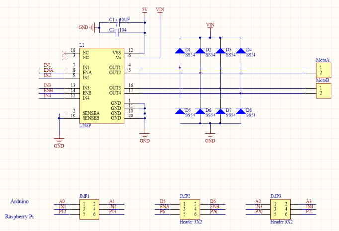
The interface of the driver:
| PIN | Raspberry Pi | Arduino |
| IN1 | P12 | A0 |
| IN2 | P13 | A1 |
| ENA | P6 | D5 |
| IN3 | P20 | A2 |
| IN4 | P21 | A3 |
| ENB | P26 | D6 |
IN1 and IN2 is connected to the left motor of AlphaBot, IN3 and IN4 are connected to the right motor of AlphaBot. ENA and ENB are the enable pins, highly active. To adjust the speed of Alphabot, you can output the PWM signal to IN1, IN2, IN3, and IN4 pins.
Control theory:
| IN1 | IN2 | IN3 | IN4 | Description |
| 1 | 0 | 0 | 1 | Motors co-rotating and Alphabot move forward |
| 0 | 1 | 1 | 0 | Motors reversing and Alphabot move backward |
| 0 | 0 | 0 | 1 | Left motor stops, and the right motor co-rotate. Alphabot turn left |
| 1 | 0 | 0 | 0 | Rightmotor stops, and the left motor co-rotate. Alphabot turn right |
| 0 | 0 | 0 | 0 | Motors stop and Alphabot stop |
Power Supply
The smart robot employs two series 18650 batteries for power supply with input voltage of 7.4V. The input voltage will be deal with the LM2596 regulator and send out to Arduino, Raspberry Pi, and sensors.

For using an external power supply, the input voltage should not beyond 12V.
AD Chip
Since the GPIO of Raspberry Pi does not support AD function, AlphaBot smart robot has an on-board 10-bit of 11 channel AD conversion chip for tracking line
application.

Obstacle avoidance module
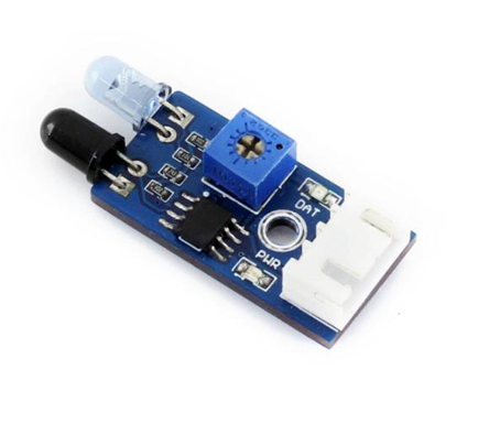
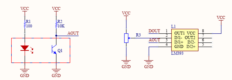
The obstacle avoidance module consists of an infrared transceiver and a comparator. The infrared transmitter has an infrared LED array as a luminophore. When there is an obstacle (reflector) on the detection direction, the Infrared light will be reflected, and received by the infrared receiver, which is a semiconductor with a PN junction made of special material as its core part. As the intensity of the infrared light enhances, more current can be generated, and the analog signal increases. LM393 comparator receives and handles the analog signal, and then outputs the relative digital signal. At this point, the green LED will light up. The logical level of the DOUT can tell you whether there is an obstacle in front of the sensor, and the output voltage of AOUT can tell you the distance from the obstacle if there is. The detection distance can be adjusted via the potentiometer knob.
Speed testing module

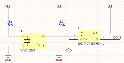
The speed testing module contains a coded disc and a WYC-H206 photoelectric sensor. WYC-H206 photoelectric sensor has an infrared transmitter and an infrared receiver. When the
infrared receiver is obscured, and unable to receive infrared light, the sensor will output a high-level voltage. The high-level voltage passes the inverting Schmitt trigger and becomes a low-level voltage. At this point, the relative indicator lights up. When the coded disc runs, DOUT will output a series of high-level pulses and low-level pulses. By checking the number of pluses in cycle time, you can get the speed of the smart robot. Here, we use the Schmitt trigger because it has a stable output signal and a clear waveform without any jitter.
Infrared remote control

The smart robot applies the LFN0038K receiver to receive an infrared signal. The infrared remote controller provided with the application kit, complies with the standard NEC encoding protocol. When the infrared receiver receives the infrared signal, it will output the relative pulses to the main control chip. Then, the main control part decodes the
signal to the key code, so as to control the corresponding motor.
Infrared NEC protocol encoding is a kind of PWM serial code, in which the binary logical“0” is in the cycle of 1.125ms with the pulse width 0.565ms and the interval 0.56ms, and the binary logical“1” is in the cycle of 2.25ms with the pulse width 0.565ms and the interval 1.685ms.

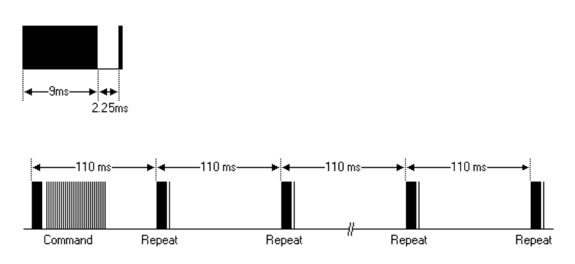
Infrared control protocol: The 32-bit binary code made up of logical “0” and logical“1” should be secondarily modulated with a 38kHz robotrier frequency, in order to enhance the transmitting efficiency and reduce power consumption. The secondary modulated code will be transmitted in the form of infrared light by an infrared transmitter, as the figure shows below

|Boot code|User ID|Radix-minus-one complement of user ID|Op code |complement of op code|
Firstly, a 9ms high-level pulse is transmitted, and a 4.5ms low-level pulse is followed. Later coming is an 8bit address code (LSB first) and its radix-minus-one complement (for checking). The last is an 8bit command code (LSB first) and its radix-minus-one complement.
Each command will only be transmitted once, even you keep pressing the key on the controller. But it will send out a duplication code every 110mS until you release the key on the controller. The format of the duplication code is a 9mS of AGC pulse, a 2.25mS of the interval, and a 560uS of the pulse.
Ultrasonic distance measurement module
The ultrasonic distance measurement module has 4 pins, they are VCC, GND, TRIG (transmitting pin) and ECHO (receive pin).
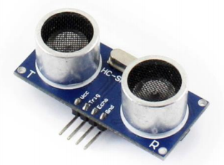
Control theory:
Here is the principle of ultrasonic distance measurement. When the ultrasonic wave meets an object, it will be reflected back and received by the receiver. You can get the distance of the object from the sensor by measuring the interval from transmitting a signal to receiving the echo.
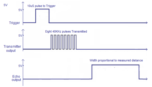
The timing diagram above shows the control principle of ultrasonic distance measurement. When the module is working, it sends out a high-level signal at least for 10us to control the pin TRIG to trigger distance measurement. Then, the module transmits 8 serials of 40kHz square wave automatically, to check whether there is an echo signal. If there is, the module outputs a high-level voltage from the pin ECHO. The time duration of the high-level voltage is the time of ultrasonic from being transmitted to reflected.
According to the sound transmitting speed and time, we can get that:measured distance=(measured time*sound speed)/2. The sound speed is 340m/s in here.
| Parameters | Remark | Min | Typ | Max | Units |
|---|---|---|---|---|---|
| Operating voltage | 3.0 | 5.5 | V | ||
| 5V operating current | Vcc=5V | 2.8 | mA | ||
| 3.3V operating current | Vcc=3.3V | 2.2 | mA | ||
| 5V ,omo,i, detectopm distance | Vcc=5V | 2 | 3 | cm | |
| 3.3V minimum detection distance | Vcc=3.3V | 2 | 3 | cm | |
| 5V maximum detection distance | Vcc=5V | 400 | 450 | 600 | cm |
| 3.3V maximum detection distance | Vcc=3.3V | 350 | 400 | 550 | cm |
| Detection angle | 15 | ° | |||
| Detection accuracy | 1 | % | |||
| Resolution | 1 | % | |||
| Output mode | GPIO | ||||
| Working temperature | -20 | 80 | °C |
Servo

Servo is an auto-control system with a DC motor, a reduction gear set, a sensor, and a control circuit. The servo can control the rotation angle of the output axis by transmitting a control signal. It has 3 control lines, the red one is the positive power line (5V), the orange one is the signal line (IO) and the brown one is power ground (GND).
Generally, a 20ms of the time-based pulse is required in controlling the servo. And the high level should be last for at least 0.5ms-2.5ms. Taking the 180 degree angle servo control as an example, the relationship between the pulse and the rotation angle is
showed as the table below.
| Pulse | Rotation angle |
| 0.5ms | 0 degree |
| 1ms | 45 degree |
| 1.5ms | 90 degree |
| 2.0ms | 135 degree |
| 2.5ms | 180 degree |
Tracker module
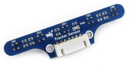
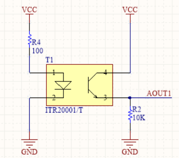
The working principle of the tracker module is similar to the infrared obstacle avoidance module. The tracker module has an ITR20001/T infrared reflection sensor, of which the infrared transmitter can transmit the infrared light all the time. When the infrared light is reflected back by the obstacle, it will be received by the infrared receiver. And the sensor will output the relative analog value. The outputted data are affected by the distance and the color of the detected object.
The tracker module has 5-channels of infrared sensors. By checking the outputs from the 5-channels of the infrared sensor, the module can judge the position of the black line, so as to control the action of the smart robot.
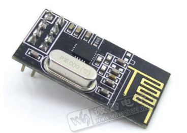
NRF24L01+ Wireless control
AlphaBot has an SPI interface that can connect with the NRF24L01 module, a new RF transceiver. The NRF24L01 has a built-in frequency synthesizer, a power amplifier, a crystal oscillator, and a modulator. With enhanced ShockBurst technology integrated, its address, output power, and communication channel can be configured by the program, suitable for multiple machine communication. The NRF24L01 has an ultra-low power consumption; when the transmitting power is within -6dBm, its working current is only 9mA, and the working current of its receiver is only 12.3mA. The NRF24L01 module also provides low power working modes, such as power-down mode and idle mode.
When using the SPI interface to configure the NRF24L01 module, you should set the module to Enhanced ShockBurstTM mode, enabling the module to handle the RF protocol automatically. Finished the configuration, the module is ready to work. The switch between receive mode and transmission mode can be done by changing the lowest byte of the command when the module is running.
The settings of the main parameters: Data width, declares the number of bits occupied by the data in the RF data package, enabling the NRF24L01+ to make a distinction between the data and the CRC code in the data package; Address width, declares the number of bits occupied by the address in the RF data package, enabling the NRF24L01+ to make a distinction between the data and the address; Receive channel, receive the address of data, the address from channel 0 to channel 5; CRC checking, NRF24L01+ can generate CRC code and perform decoding; Working frequency, configurable between 2.4GHz to 2.524GHz with the interval of 1MHz; Transmission power, affects the communication distance and the power consumption of the whole device; Communication rate, selectable of 1Mbps or 2Mbps.
Bluetooth control
AlphaBot has a UART interface, which can connect with a Bluetooth module 2.0 directly, or connect with dual Bluetooth module via the Accessory Shield module. Since the Bluetooth module is controlled via serial port, users do not need to know much about the Bluetooth protocol. When connected with the Bluetooth module , you can control your smart robot via your mobile phone
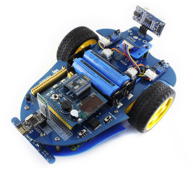
In the figure above, we can see the robot uses the dual Bluetooth module via the Accessory Shield board, supporting Bluetooth 2.0 and Bluetooth 4.0. This is the Bluetooth configuration of our application. However, the Bluetooth 2.0 for the UART interface is not provided in our application kit.
Zigbee
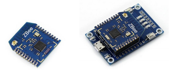
AlphaBot can connect with the Core2530 (B) module via Accessory Shield, to perform ZigBee control. In this configuration, the PC should be connected to the CC2530 Eval Kit (B) via a USB cable.
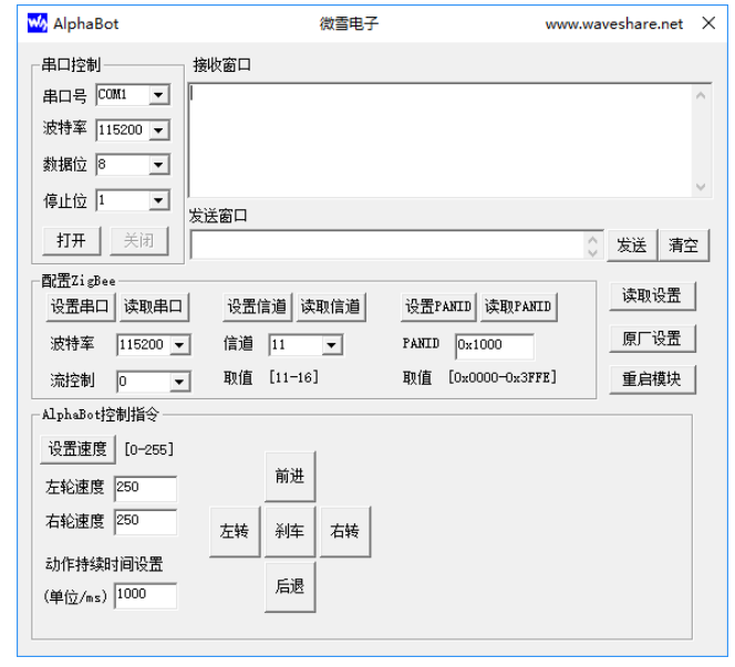
Here is the PC software for controlling the smart robot.
Wifi video monitoring
In AlphaBot application, when Raspberry Pi works as the main control part, you can use your mobile phone or PC to perform wifi video monitoring via website control. The webiopi can help you to perform the remote control, and the mjpg-streamer software can realtime display the image captured by the camera.
python-bottle is a simple but efficient python Web framerate which is based on WSCI. You can control Pi via Web page by using the Bottle.
MJPG-streamer can collect images from a webcam camera, and transmit them to the mobile device with a browser in the form of stream via the IP based network. With the software mjpg-streamer, you can see the image captured by the camera displayed on your browser via the network.
Arduino Examples
Copy the library file under the directory of Arduino to the libraries folder under the installation directory of Arduino IDE. Then, reboot Arduino IDE, and click File-> Example to check whether there are the options of AlphaBot, TRSensor, and Servo. If there are, the library has been exported successfully.
Robot testing program
1. Click File-> Example -> AlphaBot -> E01_Run_Test to open the project. Compile and download the program to the Arduino development board.
2. Connect the Jumpers IN1, IN2, ENA, ENB, IN3, and IN4 in the A area to the A0, A1, D5, D6, A2, and A3, respectively.
- Turn on the power adapter, you can see that the smart robot runs straight forward.
If the wheels of the smart robot are not forward running, you can try to change the wiring of the motor, or modify the pin set in the AlphaBot.c file.
Infrared obstacle avoidance program
1. Click File -> Example -> AlphaBot -> E02_Infrared_Obstacle_Avoidance to open the project. Compile and download the program to the Arduino development board.
2. Install the Infrared Proximity Sensors to the left side and the right side of the smart robot. Connect the jumper of the motor in A area to the Arduino, and the jumpers DL
and DR of E area to D7 and D8, respectively.
- Turn on the power adapter, you can see that the smart robot can perform infrared obstacle avoidance.
When the sensor detected the obstacle ahead of the robot, the green LED will light up. The detection distance can be adjusted by a potentiometer. When the left sensor detects the obstacle, the smart robot will turn to the right. When the right sensor detects the obstacle, the smart robot will turn to the left
Infrared tracking program
1. Click File -> Example -> AlphaBot -> E03_Infrared_Tracking_Objects to open the project. Compile and download the program to the Arduino development board.
2. Install the Tracker Sensor to the smart robot. Connect the jumper of the motor in A area to the Arduino, and the jumpers DL and DR of E area to D7 and D8, respectively.
- Turn on the power adapter, you can see that the smart robot can perform object tracking.
If there is an object in front of the smart robot, the robot will run forward. If there is nothing in front of the robot, the smart robot will stand. The detection distance can be adjusted by potentiometer.
Infrared remote control program
1. Click File -> Example -> AlphaBot -> E04 Infrared_Remote_Control to open the project. Compile and download the program to the Arduino development board.
2. Connect the jumper of the motor in A area to the Arduino, and the jumper of the Infrared receiver IR in G area to the jumper D4 on Arduino.
- Expectation result:
When pressed the key on the Infrared remote controller, you can control the smart robot. The key 2 is for go forwards, 8 for going backward, 4 for turn left, 6 for turn right, 5 for stop, - for speed down, and + for speed up. (Notes: The key encoding may change with different Infrared remote controller. You can modify the program as required. )
Ultrasonic distance measurement program
1. Click File-> Example->AlphaBot-> E05_Ultrasonic_Ranging to open the project. Compile and download the program to the Arduino development board.
2. Install the servo and Ultrasonic module to the smart robot. Connect the jumpers TRIG, ECHO of the Ultrasonic unit in the D area to the pins D11 and D12 on the Arduino. (The tracking line function will use these pins as well, so please remove the corresponding jumpers, avoiding interruption).
- Turn on the power adapter, the screen will show the distance measured by the Ultrasonic unit currently.
Ultrasonic obstacle avoidance program (without servo)
1. Click File-> Example -> AlphaBot -> E06_Ultrasonic_Obstacle_Avoidance1 to open the project. Compile and download the program to the Arduino development board.
2. Install the steering gear and Ultrasonic module to the smart robot. Connect the jumpers TRIG, ECHO of Ultrasonic unit in D area to the pins D11 and D12 on the Arduino.
- Turn on the power adapter, the smart cat can perform ultrasonic obstacle avoidance.
When there is an obstacle in front of the robot, it will move to the side that far away from the obstacle.
Ultrasonic obstacle avoidance program (with servo)
1. Click File-> Example -> AlphaBot -> E07_Ultrasonic_Obstacle_Avoidance2 to open the project. Compile and download the program to the Arduino development board.
2. Install the servo and Ultrasonic module to the smart robot. Connect the jumpers TRIG, ECHO of the Ultrasonic unit in the D area to the pins D11 and D12 on the Arduino. Connect the jumpers S1 and S2C of the servo in the C area to the pins D9 and D10 on the Arduino. (The tracking line function will use these pins as well, so please remove the corresponding jumpers, avoiding interruption).
- Turn on the power adapter, the smart cat can perform ultrasonic obstacle avoidance.
When there is an obstacle in front of the robot, the Ultrasonic module will measure the distance from the right side and the left side of the robot to the obstacle, respectively. Then, it will move to the side that far away from the obstacle
Infrared tracking line program
1. Click File -> Example -> AlphaBot -> E08_Infrared_Line_Tracking to open the project. Compile and download the program to the Arduino development board.
2. Install the Tracker Sensor to the smart robot. Connect the jumper of the motor in A area to the Arduino, and the jumpers CLK, ADDR, DOUT, and CS of F area to D13, D12, D11, and D10, respectively. (The servo in C area and the ultrasonic unit in D area will use these pins as well, so please remove the corresponding jumpers, avoiding interruption).
3. The tracking line program enables the smart robot run along the black line with the background color of white. You can choose a black adhesive tape with 15cm width, and paste it to a white KT board to create the smart robot tracking line scenario. The dark background color will reduce the capability of the smart robot on the tracking line.
4. Turn on the power adapter, and hold the robot in the middle of the black line and close to the ground, then swing the robot from side to side. The
smart robot goes into the calibration mode, identifying the max. and min. threshed of each sensor. Calibration can have a direct influence to the tracking line capability of the smart robot. When the wheels of the robot begin to move, you can release the robot and it will run along with the black line.
For more detailed information about the control theory and the algorithm, please refer to the Tracker Sensor User Manual.
Bluetooth remote control program
1. Click File-> Example -> AlphaBot -> E09_Bluetooth_Control to open the project. Compile and download the program to the Arduino development board.
2. Install the Accessory Shield module to the smart robot via the Arduino interface and the Bluetooth module to the Accessory Shield module via the XBee interface.
- Turn on the power adapter, and download and install the Bluetooth control software to your mobile phone. :
Run the software and connect with the Bluetooth, then you can control the motion of the smart robot with the direction keys. OLED can display the command string that you sent.
ZigBee remote control program
1. Click File -> Example -> AlphaBot -> E10_Zigbee_Control to open the project. Compile and download the program to the Arduino development board.
2. Install the Accessory Shield module to the smart robot via the Arduino interface and the ZigBee module Core2530 (B) to the Accessory Shield module via the XBee interface. Connect the CC2530 Eval Kit5 development kit to your PC with a USB cable.
- Turn on the power adapter, and open the AlphaBot.exe on your PC, select the corresponding serial port number.
Then you can control the motion of a smart robot with the direction keys. OLED can display the command string that you sent.
- Here is the PC software for controlling the smart robot.
Raspberry Pi Example Program (AlphaBot-Pi)
Python demo also is provided.
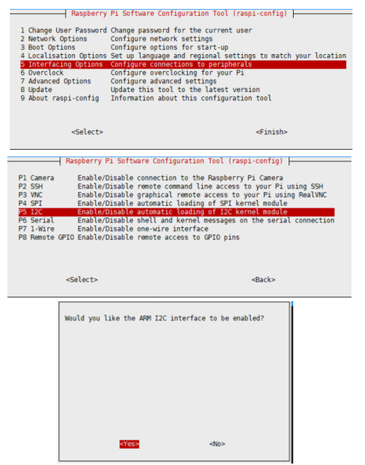
Enable SPI interface
- Open the terminal, and use the command to enter the configuration page.
sudo raspi-config
Choose Interfacing Options -> SPI -> Yes  to enable the SPI interface
sudo reboot
Make sure that the SPI is not occupied by other devices, you can check in the middle of the /boot/config .txt.
- Check /boot/config.txt, and you can see 'dtparam=spi=on' was written in.
- To make sure SPI is not occupied, it is recommended to close other drivers' coverage. You can use ls /dev/spi* to check whether SPI is occupied. If the terminal outputs /dev/spidev0.1 and /dev/spidev0.1, SPI is not occupied.
Enable I2C Interface
Open a terminal and run the following commands:
sudo raspi-config
Choose Interfacing Options -> I2C -> Yes.
Reboot Raspberry Pi:
sudo reboot
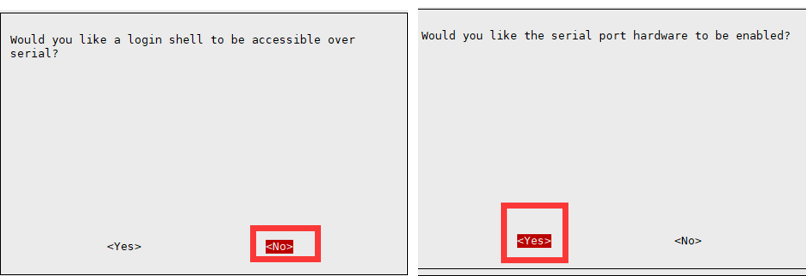
Enable UART interface
Open the Raspberry Pi terminal and enter the following command to enter the configuration interface
sudo raspi-config
Select Interfacing Options -> Serial, disable shell access, and enable the hardware serial port
Install Libraries
- python2
sudo apt-get update
sudo apt-get install ttf-wqy-zenhei
sudo apt-get install python-pip
sudo pip install RPi.GPIO
sudo pip install spidev
sudo apt-get install python-smbus
sudo apt-get install python-serial
sudo pip install rpi_ws281x
- python3
sudo apt-get update
sudo apt-get install ttf-wqy-zenhei
sudo apt-get install python3-pip
sudo pip3 install RPi.GPIO
sudo pip3 install spidev
sudo apt-get install python3-smbus
sudo apt-get install python3-serial
sudo pip3 install rpi_ws281x
Download Examples
wget https://files.waveshare.com/upload/3/39/AlphaBot2-Demo.zip
unzip AlphaBot2-Demo.zip
Motor Test
Run in the terminal of the Raspberry Pi:
cd /home/pi/AlphaBot2-Demo/RaspberryPi/AlphaBot2/python/
sudo python AlphaBot2.py
- Expected result: After the program runs, the motor rotates and the trolley moves forward.
- If the direction is wrong, you need to modify the motor wiring accordingly or modify the pins in the program. The second method is recommended. If the rotation direction of the left wheel is not correct, then ain1 and ain2 will be used. If the rotation direction of the right wheel is not correct, then switch bin1 and bin2.
def __init__(self,ain1=12,ain2=13,ena=6,bin1=20,bin2=21,enb=26):
Joystick Direction
Run in the terminal of the Raspberry Pi:
cd /home/pi/AlphaBot2-Demo/RaspberryPi/AlphaBot2/python/
sudo python Joystick.py
- Expected result: Joystick Joystick in 5 directions, including up, down, left, right, and OK. When the button is pressed, the control port will display the key position of the current button, the motor will rotate according to the direction of the button, and the buzzer will sound.
- If the rotation direction of the wheel is different from the direction of the button, you need to modify the pin.
IR Remote Control Car
Run in the terminal of the Raspberry Pi:
cd /home/pi/AlphaBot2-Demo/RaspberryPi/AlphaBot2/python/
sudo python IRremote.py
- Expected result: Press the number keys of the infrared remote control to control the car. 2, 8, 4, 6, and 5 respectively represent forward, backward, turn left, turn right, and stop. Press - or + to adjust the speed. (Note: Different infrared remote controllers may have different key codes, if they are different, you need to modify the corresponding program.)
Infrared Obstacle Avoidance
Run in the terminal of the Raspberry Pi:
cd /home/pi/AlphaBot2-Demo/RaspberryPi/AlphaBot2/python/
sudo python Infrared_Obstacle_Avoidance.py
- When there is no obstacle before the car, the front green LED will turn off. When the car encounters an obstacle, the green LED light in front will light up. If the LED is not on or is always on, you can adjust the two potentiometers on the bottom of the trolley so that the LED is just off.
- Expected result: If the sensor on the left side of the car does not reach an obstacle, the car will go straight and turn left when an obstacle is detected.
Ultrasonic Ranging (the Raspberry Pi 3B package does not include the ultrasonic module)
- Run in the terminal of the Raspberry Pi:
cd /home/pi/AlphaBot2-Demo/RaspberryPi/AlphaBot2/python/
sudo python Ultrasonic_Ranging.py
- Expected results: the terminal will display the current measuring distance.
Ultrasonic Obstacle Avoidance (Raspberry Pi 3B package does not include ultrasonic module)
Run in the terminal of the Raspberry Pi:
cd /home/pi/AlphaBot2-Demo/RaspberryPi/AlphaBot2/python/
sudo python Ultrasonic_Obstacle_Avoidance.py
- Expected result: If the sensor on the left side of the car does not reach an obstacle, the car will go straight and turn right when an obstacle is detected.
RGB Light
Run in the terminal of the Raspberry Pi:
cd /home/pi/AlphaBot2-Demo/RaspberryPi/AlphaBot2/python/
sudo python ws2812.py
- Expected result: there are four RGB LEDs on the bottom of the car: Red, Green, Blue, and Yellow.
If the displayed color is wrong, you can add the following statement to the /boot/config.txt file, and then restart to take effect. Since the RGB LEDs are controlled by DMA and the audio output of the Raspberry Pi is a DMA channel, the following statement will disable the headphone port.
hdmi_force_hotplug=1
hdmi_force_edid_audio=1
Tracking Sensor Test
Run in the terminal of the Raspberry Pi:
cd /home/pi/AlphaBot2-Demo/RaspberryPi/AlphaBot2/python/
sudo python TRSensors.py
- Expected result: The terminal prints five sets of data, corresponding to five sensors respectively. When the car is placed on the white bottom plate, the value is about eight or nine hundred. The number is about one hundred to three hundred.
IR Tracking Program
Run in the terminal of the Raspberry Pi:
cd /home/pi/AlphaBot2-Demo/RaspberryPi/AlphaBot2/python/
sudo python Line_Follow.py
- Expected result: When the program is running, it will rotate left and right for automatic calibration. After the calibration is completed, move the Alphabot2 left and right, and the terminal will display the current position of the black line and the values of the five sensors. Straighten the car, and press the button in the middle of the five-way joystick, the car will move along the black line, and the RGB LED at the bottom of the car will display different colors.
Servo
Run in the terminal of the Raspberry Pi:
cd /home/pi/AlphaBot2-Demo/RaspberryPi/AlphaBot2/python/
sudo python PCA9685.py
- Expected result: the servo will move left and right, and the rotation range is about 180 degrees.
MJPG-streamer Software Real-time Monitoring
"MJPG-streamer", is an open-source project which is used to capture images from the camera, and transmit the video data to a webpage via the network.
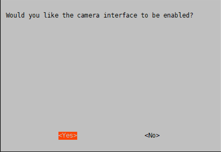
- To use the camera, you need to first enable the camera
sudo raspi-config
*Choose Enable Camera -> Yes
- If it is a camera using the CSI interface, the system cannot find the device node of /dev/video0. A line for bcm2835-v4l2 needs to be added to the /etc/modules file:
sudo nano /etc/modules
- Append the line to the file
bcm2835-v4l2
- Reboot and check the device:
sudo reboot
ls /dev/video*
video0 device will be listed as expected.
Note: After performing the first steps, please confirm that the operation and instructions are correct.
- Run the following commands:
cd /home/pi/AlphaBot2-Demo/RaspberryPi/AlphaBot2/
sudo apt-get update
sudo apt-get install cmake libjpeg9-dev
git clone https://github.com/jacksonliam/mjpg-streamer
cd mjpg-streamer/mjpg-streamer-experimental/
sudo make clean all
sudo ./start.sh
Open a Chorme, and go to Ip_address:8080, click stream to check the camera.
For more information about the mjpg-streamer:https://github.com/jacksonliam/mjpg-streamer

Remotely Control Alphabot By Bottle
"Bottle" is a simple and efficient WSGI-compliant micro python web framework. You can quickly implement web control with Bottle.
Run the following commands in the terminal:
Python2:
sudo apt-get install python-bottle
Python3:
sudo apt-get install python3-bottle
- Web Control RGB LED via Bottle
cd /home/pi/AlphaBot2-Demo/RaspberryPi/AlphaBot2/Web-RGB
sudo python main.py
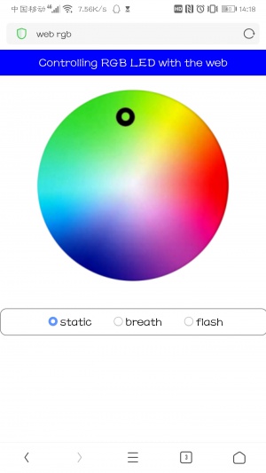
Enter the IP address of the Raspberry Pi in the address bar of the mobile phone browser (computer browsers are not supported), the port number is 8002, and the following page will be displayed. By clicking on different positions of the picture, the RGB LED will display different colors. "static", "breath", and "flash" correspond to three display modes respectively.
- Realize web video control the car through Bottle.
cd /home/pi/AlphaBot2-Demo/RaspberryPi/AlphaBot2/Web-Control
sudo python main.py
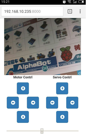
Open Chrome, and go to Ip_address:8000, click stream to check the camera.

You can control it by telephone or PC.
Control it by telephone:
- To set it to autostart, you can modify /etc/rc. local file and add the following lines
sudo nano /etc/rc.local
#Without the nano editor, enter the following command to download
sudo apt-get install nano
Add:
cd AlphaBot_Demo/AlphaBot_Demo/RaspberryPi/AlphaBot/Web-Control
sudo python main.py &
Finally, edit main.py. This step is very important. If it is not set, the program will not be able to run after booting. This step is to wait for the host to connect to the network and the added delay.
sudo nano /home/pi/AlphaBot2-Demo/RaspberryPi/AlphaBot2/Web-Control/main.py
#Find the 23rd line, delete the # sign in front of time.sleep(12), if your system boots slowly, you can increase the parameters in parentheses
As we know, the IP address of Raspberry Pi is dynamic and changes all the time. You can configure static IP by modifying the /etc/dhcpcd.conf file.
interface wlan0
static ip_address = 192.168.1.114/24
static routers = 192.168.1.1
192.168.1.1 is the IP address of the router and 192.168.1.114 is the static IP set, /24 should be added in the end
Note:
You need to set the jumpers IN1, IN2, ENA, ENB, IN3, and IN4 which are in the A area to P12, P13, P6, P26, P20, and P21 for controlling Alphabot by Pi. The jumpers S1, and S2 of the C areas should be connected to P27 and P22. After rebooting, you can go to ip_address:8000 to enter the control webpage.
Remote Control Alphabot2 With The Software
- Control the car through the mobile phone or PC software video.
cd /home/pi/AlphaBot2-Demo/RaspberryPi/AlphaBot2/App-Control
sudo python main.py
- Open another terminal and run mjpg-streamer
cd /home/pi/AlphaBot2-Demo/RaspberryPi/AlphaBot2/mjpg-streamer/mjpg-streamer-experimental
sudo ./start.sh
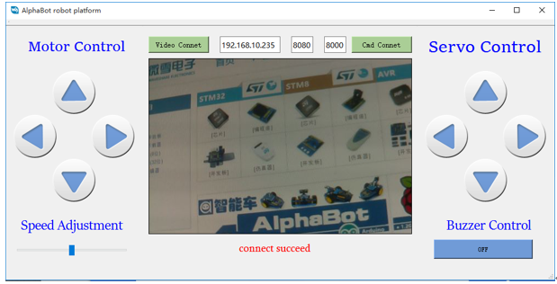
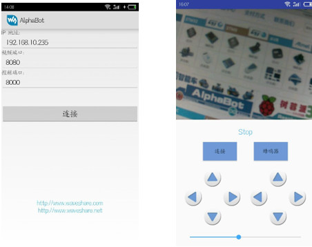
Open the AlphaBot.exe program on the computer, enter the IP address, the port number of mjpg-stream, and the port number of the car Soket server.
Click Video Connet to connect the video, the button turns green and the connection is successful, click Cmd Connect to the car server. If the button turns green, the connection is successful. The button on the left controls the movement of the car, and the button on the right controls the rotation of the camera servo.
Scan the QR code below with your mobile phone to download the corresponding APP.

If it fails, please click here to download [APP https://files.waveshare.com/upload/5/53/Alphabot_app.zip]
Enter the actual address of the Raspberry Pi, click the link to see the image captured by the camera, click the connection, after the button changes from green to blue, it indicates the control port connection program, the corresponding button of the motor can control the movement of the car, the rotation of the servo, and pull the slider to Change the trolley speed.
Open the /etc/rc.local file with a text editor and add the following command to set the boot to start.
sudo nano /etc/rc.local
#There is no nano editor, enter the following command to download
sudo apt-get install nano
Add the following command between fi and exit 0, then save the file and exit.
cd /home/pi/mjpg-streamer/mjpg-streamer-experimental
sudo ./start.sh &
cd /home/pi/AlphaBot2-Demo/RaspberryPi/AlphaBot2/App-Control
sudo python main.py &
Finally, edit main.py. This step is very important. If it is not set, the program will not be able to run after booting. This step is to wait for the host to connect to the network and the added delay.
sudo nano /home/pi/AlphaBot2-Demo/RaspberryPi/AlphaBot2/APP-Control/main.py
#Find the 15th line, delete the # sign in front of time.sleep(8). If your system boots slowly, you can increase the parameters in the parentheses
Every time the Raspberry Pi starts, it needs to connect to the router. Of course, we can also enable the AP function of the Raspberry Pi wireless network adapter and use the Raspberry Pi as a router. For details, please refer to the Raspberry Pi tutorial, which will not be described in detail here.
Remote Control Car Via Raspberry Pi Bluetooth
- Upgrade and install Bluetooth-related software packages, and install Bluetooth dependency library.
sudo apt-get update
sudo apt-get upgrade -y
sudo apt-get dist-upgrade -y
sudo apt-get install pi-bluetooth bluez bluez-firmware blueman
- Add a Pi user to the Bluetooth group.
sudo usermod -G bluetooth -a pi
- Reboot the Raspberry Pi.
sudo reboot
- Start/increase SPP, and turn on Bluetooth device.
sudo vi /etc/systemd/system/dbus-org.bluez.service
Modify these two statements in the file.
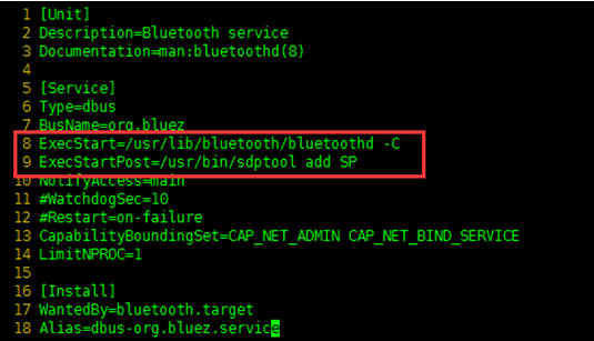
After rebooting the Raspberry Pi, you can enter the command "hciconfig" (similar to "ifconfig" command) to check the Bluetooth service.

If you can see "hci0" device, the Bluetooth is enabled to work. If not, the Bluetooth device is not identified.
Note: If there is dtoverlay=pi3-miniuart-bt in the /boot/config.txt file, this statement needs to be commented out, otherwise the Bluetooth device will not work properly.
- Connect to the Bluetooth device
Enter the following command to enter the Bluetooth control interface. (input "help" to enter the interface to check the command list.)
sudo bluetoothctl
agent on
After entering the interface: (input "help" to enter the interface to check the command list.)
agent on
default-agent
After "scan on", you can see the physical address of the scanned Bluetooth devices, that is, Addresses like XX:XX:XX:XX:XX:XX.

Use the following command for pairing (please replace XX:XX:XX:XX:XX:XX with the address of your own device, Android phone can see the Bluetooth address in Settings->About Phone->Status Information.)
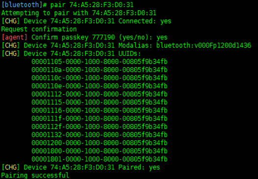
Add the device to the trusted list after pairing.
trust XX:XX:XX:XX:XX:XX
connect XX:XX:XX:XX:XX:XX

Finally, click "quit" to exit. After the Bluetooth device is turned on, the Raspberry Pi will automatically connect.
Note: If the link under the command line is unsuccessful, you can connect under the graphical interface.
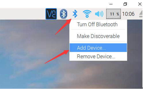
Click the Bluetooth icon to add a Bluetooth device.
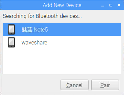
Select the corresponding mobile phone Bluetooth device, note that the mobile phone Bluetooth must be turned on to be discoverable.
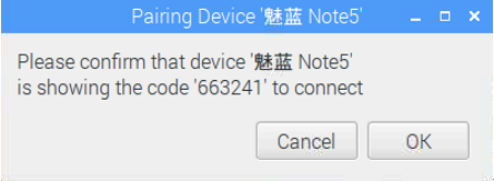
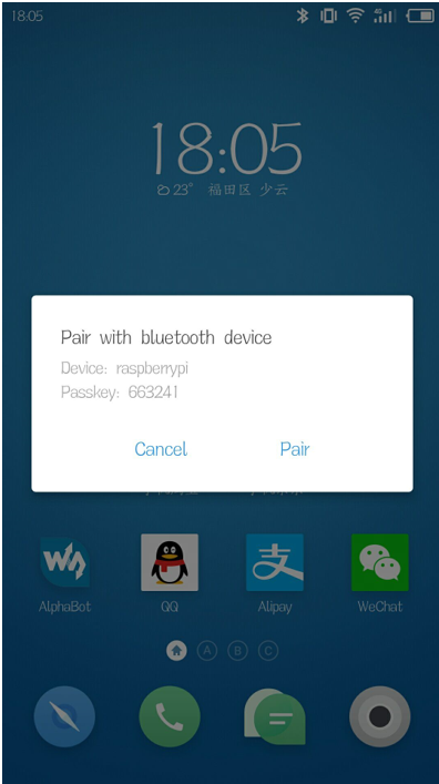
On the Raspberry Pi side, select ok for pairing, and on the mobile phone side, select "Pair" for pairing.
It prompts that the configuration is successful, but there is no service.

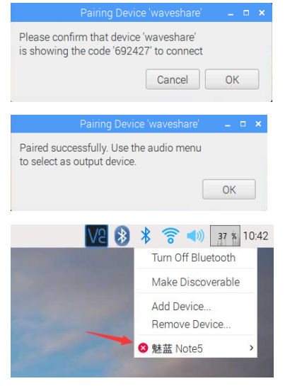
Connected successfully. Run the following command to start the program:
cd AlphaBot2-Demo/RaspberryPi/AlphaBot2/Bluetooth-Control
sudo rfcomm watch hci0 1 python bluetooth.py
Scan the QR code below with your mobile phone to download the corresponding APP. (This software is Dual-mode Bluetooth module control software. If this software has been installed in the above Arduino operation, it is not necessary to install it again.)

If it fails, you can click here to download.
Start the APP, and click "Scan" (Note: the mobile phone needs to turn on the Bluetooth function), the corresponding Bluetooth devices will be displayed in the list normally. Select the "raspberrypi" device. Go to the next page and select "Remote Mode" to enter the remote mode.

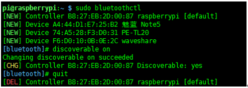
If the Raspberry Pi Bluetooth is not found, you can run the following command to enable Bluetooth discovery.
Safety Precautions
Product name: Smart robot extension development kit, contains AlphaBot baseboard, and smart robot baseboard. Support Arduino and Raspberry Pi development boards.
To prevent AlphaBot, a precision device, from breaking down or being damaged, please follow the requirement listed below.
- The product employs two series 14500 batteries for power supply with an input voltage of 7.4V. When working with Arduino and Raspberry Pi at the same time, the external power supply should be applied. Any external power supply has to obey the regulations and standards of power supply for your area.
- The product should be applied under a well-ventilated environment, to guarantee the heat dissipation of the power supply and product performance.
- The disassembly chassis should be placed on a stable, flat, and non-conducting surface, without touching any conductive materials.
- The chassis can be connected to either Raspberry Pi or Arduino, or connected to both of them. Arduino and Raspberry Pi should not touch each other, in case of working together.
- Installing the incompatible device to the chassis may cause damage and void the warranty.
- The product should not expose to water and moisture, or not be placed on a conductive surface, in the course of any operations.
- AlphaBot should not touch any heat source, to make sure reliable service under a normal room temperature environment.
- Protect the printed circuit board and the components on it from mechanical or electrical damages, in the course of any operations.
- Avoid touching the energized printed circuit board in the course of any operations. Touching the edge of the board is allowed, which can reduce the risk of electrostatic discharge.
Video
Related products
Resources
- AlphaBot2-Ar User Guides
- AlphaBot2-Pi User Guides
- AlphaBot2-PiZero User Guides
- AlphaBot2 for micro:bit User Guides
Documentation
| AlphaBot2-Base: | Schematic | |
| AlphaBot2-Ar: | Schematic | Assembly diagram |
| AlphaBot2-Pi: | Schematic | Assembly diagram |
| AlphaBot2-PiZero: | Schematic | Assembly diagram |
| AlphaBo2 for micro:bit | Schematic | Assembly diagram |
Demo codes
Image
Software
- PuTTY for serial debugging
- SecureCRT for serial debugging
- Bluetooth Apps: iOS, Android
- Windows Qt client
- WiFi video console for Android
Note: You should download the archive and unzip it to get the Android apk. Copy the apk file to your phone and install.
- AI in Robotics -- This is an AI applications shared by Shaun Price
FAQ
AlphaBot2 is smaller in size, highly integrated with various sensors, and more stable in structure. With a high-precision all-metal motor, it boasts low noise and high precision. Compared with L298P, its TB6612FNG motor driver chip is more efficient, smaller, and does not heat up. Also, it added peripherals such as buttons, buzzers, cool lights, USB to a serial port, etc., which is more convenient for you. AlphaBot2-Ar adapter board adds OLED, AlphaBot2-PiZero adapter board adds USB Hub and PCA9685 servo control chip to avoid the jitter phenomenon of Raspberry Pi software PWM control servo. The programs are more abundant, and the Raspberry Pi adds Android App video control and Qt software control on the computer. Also adds onboard Bluetooth remote control for Raspberry Pi.
{{{5}}}
Support a 14500 battery (not included), that is, 14mm directly and 50mm in length. The standard voltage of a single cell is generally 3.7V, the fully charged voltage is generally 4.2V, and the minimum voltage cannot be lower than 3V or 2.75V, otherwise, the battery will be permanently damaged. The shape of this battery is the same as the size of the AA battery, but it cannot be replaced by the AA battery. The 5th battery voltage is not enough.
{{{5}}}
{{{5}}}
{{{5}}}
{{{5}}}
{{{5}}}
{{{5}}}
{{{5}}}
{{{5}}}
Technical Support
If you need technical support or have any feedback/review, please click the Submit Now button to submit a ticket, Our support team will check and reply to you within 1 to 2 working days. Please be patient as we make every effort to help you to resolve the issue.
Working Time: 9 AM - 6 PM GMT+8 (Monday to Friday)


