1.5inch OLED Module old
Relative Resource
Raspberry Pi
Provide C and python demos.
Working with Raspberry PI
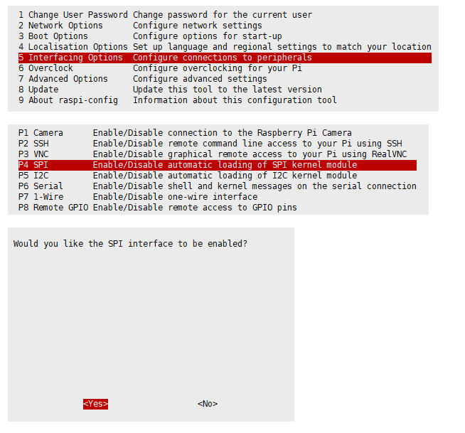
Enable SPI Interface
- Open the Raspberry PI terminal, use the following command to enter the configuration interface.
sudo raspi-config
Choose Interfacing Options -> SPI -> Yes to enable SPI interface

And then reboot the Raspberry Pi.
sudo reboot
Please make sure the SPI is not occupied by other devices, you can check in the middle of /boot/config.txt.
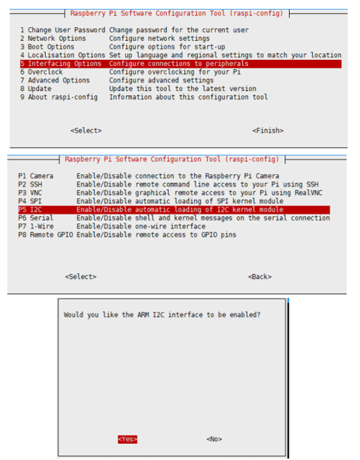
Enable I2C interface
- Open the Raspberry PI terminal, use the following command to enter the configuration interface.
sudo raspi-config
Choose Interfacing Options -> I2C -> Yes to enable i2C kernel driver

And then reboot the Raspberry Pi.
sudo reboot
Install Library
If you use bookworm system, you can only use lgpio library, bcm2835 and wiringPi can't be installed and used.
BCM2835
#Open the Raspberry Pi terminal and run the following command:
wget http://www.airspayce.com/mikem/bcm2835/bcm2835-1.71.tar.gz
tar zxvf bcm2835-1.71.tar.gz
cd bcm2835-1.71/
sudo ./configure && sudo make && sudo make check && sudo make install
#For more, you can refer to the official website: http://www.airspayce.com/mikem/bcm2835/
WiringPi
#Open the Raspberry Pi terminal and run the following command:
cd
sudo apt-get install wiringpi
#For Raspberry Pi systems after May 2019 (earlier than that do not need to execute), an upgrade may be required:
wget https://project-downloads.drogon.net/wiringpi-latest.deb
sudo dpkg -i wiringpi-latest.deb
gpio -v
#Run gpio -v and version 2.52 will appear, if it does not appear, it means there is an installation error.

#The Bullseye branch system uses the following command:
git clone https://github.com/WiringPi/WiringPi
cd WiringPi
./build
gpio -v
#Run gpio -v and version 2.70 will appear, if it does not appear, it means there is an installation error.
lgpio
#Enter the Raspberry Pi and run the following commands:
wget https://github.com/joan2937/lg/archive/master.zip
unzip master.zip
cd lg-master
sudo make install
#For Raspberry Pi 5
sudo apt install python3-rpi-lgpio
#For more details, you can refer to the official website: https://github.com/gpiozero/lg
- Python
sudo apt-get updata
sudo apt-get install python-pip
sudo pip install RPi.GPIO
sudo apt-get install python-smbus
sudo pip install spidev
Download the Demo
Open the Raspberry Pi terminal and run:
sudo apt-get install p7zip-full
wget https://files.waveshare.com/upload/9/9d/1.5inch_OLED_Moudle.7z
7z x 1.5inch_OLED_Moudle.7z  -r -o./1.5inch_OLED_Moudle
sudo chmod 777 -R  1.5inch_OLED_Moudle
cd 1.5inch_OLED_Moudle/Raspberry/
Hardware Connection
| LCD | Raspberry Pi BCM |
| VCC | 5V |
| GND | GND |
| DIN | MOSI |
| CLK | SCK |
| CS | CE0 |
| DC | 24 |
| RST | 25 |
SPI Demo (default)
- C
cd C
make clean
make
sudo ./main
- python
cd python
#python2
sudo python main.py
#python3
sudo python3 main.py
I2C Control
- The default 4-wire SPI is used. If the hardware is modified to I2C, the program needs to be modified.
| OLED | Raspberry Pi |
| DIN | SDA |
| CLK | SCL |
C
Open C\obj\DEV_Config.h, modify the following:
#define USE_SPI 1
#define USE_IIC 0
to:
#define USE_SPI 0
#define USE_IIC 1
And then re-execute:
make clean
make
sudo ./main
python
Open python/config.py, modify the following:
Device_SPI = 1
Device_I2C = 0
to:
Device_SPI = 0
Device_I2C = 1
And then re-execute:
sudo python main.py
Working with STM32
This demo uses the development board XNUCLEO-F103RB and is based on the HAL library.
Hardware Connection
| LCD | XNUCLEO-F103RB |
| VCC | 5V |
| GND | GND |
| DIN | PA7 |
| CLK | PA5 |
| CS | PB6 |
| DC | PA8 |
| RST | PA9 |
Switch SPI and I2C
Two macros are defined in DEV_Config.h: USE_SPI_4W and USE_IIC. If the I2C control is used, set USE_IIC to 1 and USE_SPI_4W to 0. If the four-wire SPI control is used, USE_IIC is set to 0 and USE_SPI_4W is set to 1.
Similarly, the connection on the hardware needs to be changed to connect to the I2C interface.
DIN-PB9
CLK-PB8
Expected Effect
Open the serial debugging tool and configure correctly, after resetting the development board, the relevant information will be printed, OLED will first brush the screen, and then display the common functions, such as drawing dot, drawing line, drawing frame, drawing picture and displaying words for 2s, and then display bitmap, 16-bit gray scale map and display time (dynamic analog clock).
Working with Arduino
- The development board used in this demo is Arduino UNO.
Hardware Connection
| LCD | UNO |
| VCC | 5V |
| GND | GND |
| DIN | D11 |
| CLK | D13 |
| CS | D10 |
| DC | D7 |
| RST | D8 |
| BL | D9 |
Switch SPI and I2C
Two macros are defined in DEV_Config.h: USE_SPI_4W and USE_IIC. If the I2C control is used, set USE_IIC to 1 and USE_SPI_4W to 0. If the four-wire SPI control is used, USE_IIC is set to 0 and USE_SPI_4W is set to 1.
Similarly, the connection on the hardware needs to be changed to connect to the I2C interface.
DIN-D14
CLK-D15
Usage
- Configure the communication mode:
Two macros are defined in DEV_Config.h: USE_SPI_4W and USE_IIC. If the I2C control is used, set USE_IIC to 1 and USE_SPI_4W to 0. If the four-wire SPI control is used, USE_IIC is set to 0 and USE_SPI_4W is set to 1.
- Configure RAM:
Three macros are defined in OLED_Driver.h to select the control mode, which can be found as follows:
#define USE_INT_RAM 1
#define USE_EXT_RAM 0
#define USE_OLED_RAM 0
They are using the internal RAM of the controller, using the external RAM and using the OLED RAM.
The internal RAM differs according to the Arduino model:
The demo uses UNO control, so OLED_BUFSIZ is only 64 * 16 bytes, occupies 1K size, if you want to display full screen, OLED_BUFSIZ needs 8K size. If you use external RAM control, you only need to set USE_EXT_RAM to 1 and set the other two to 0. Regarding the use of OLED RAM, because OLED controller can not read the data in the buffer when using serial port communication, the definition here is only for compatibility with other OLEDs, no other special significance.
Phenomenon
Compile and download to the development board.
Open the serial debugging tool and configure correctly, after resetting the development board, the relevant information will be printed, OLED will first brush the screen, and then display the common functions, such as drawing dot, drawing line, drawing frame, drawing picture and displaying words for 2s, and then display bitmap, 16-bit gray scale map and display time (dynamic analog clock).
Working with Jetson nano
Install Library
Install Function Library
- Open the terminal interface, enter the following command to install the corresponding function library:
sudo apt-get update
sudo apt-get install python3-pip
sudo pip3 install Jetson.GPIO
sudo groupadd -f -r gpio
sudo usermod -a -G gpio your_user_name
sudo cp /opt/nvidia/jetson-gpio/etc/99-gpio.rules /etc/udev/rules.d/
sudo udevadm control --reload-rules && sudo udevadm trigger
【Note】 your_user_name is the user name you use, such as waveshare.
- Install I2C
sudo apt-get install python-smbus
- Install image processing library:
sudo apt-get install python3-pil
sudo apt-get install python3-numpy
Download the Demo
sudo apt-get install p7zip
wget https://files.waveshare.com/upload/9/9d/1.5inch_OLED_Moudle.7z
7zr x 1.5inch_OLED_Moudle.7z -r -o./1.5inch_OLED_Moudle
sudo chmod 777 -R  1.5inch_OLED_Moudle
cd 1.5inch_OLED_Moudle/Jetson\ Nano/
Hardware Connection
| LCD | Jetson nano(BCM) |
| VCC | 5V |
| GND | GND |
| DIN | MOSI |
| CLK | SCK |
| CS | CE0 |
| DC | 24 |
| RST | 25 |
I2C Control
- Jetson nano currently only supports I2C control, modify the corresponding hardware connection:
| OLED | Jetson nano |
| DIN | SDA |
| CLK | SCL |
C
Open C\obj\DEV_Config.h, modify the following:
#define USE_SPI 1
#define USE_IIC 0
to:
#define USE_SPI 0
#define USE_IIC 1
And then re-execute:
make clean
make
sudo ./main
python
Open python2/config.py, modify the following:
Device_SPI = 1
Device_I2C = 0
to:
Device_SPI = 0
Device_I2C = 1
And then re-execute:
sudo python main.py
Same with python3.
