0.71inch LCD Module
| ||
Overview
Introduction
The 0.71inch circular LCD module features an IPS display, with 160 x 160 pixels, equipped with an integrated GC9D01 driver chip, and utilizes SPI interface communication. It is suitable for integration into controllers such as ESP32, Raspberry Pi Pico, Arduino, etc., and can be used in creative applications like simulated electronic eyes or wearable devices.
Specifications
| Operating voltage | Communication interface | Display panel | Control chip |
|---|---|---|---|
| 3.3V/5V | 4-wire SPI | IPS | GC9D01 |
| Resolution | Display size | Pixel pitch | Dimensions |
| 160 × 160 pixels | 18 × 18 (mm) | 37.5 × 112.5 (μm) | 20.12 × 22.3 (mm) |
Pin Definition
Operating Principle
LCD and its Controller
This LCD uses the built-in GC9D01 driver, with a resolution of 160×160. It has an internal GRAM and supports 12/16/18-bit data bus MCU interfaces, i.e., RGB444, RGB565, RGB666 three color formats, which are common RGB formats.
For most LCD controllers, the communication interface can be configured, including 8080 parallel, 3-wire SPI, 4-wire SPI, etc. This LCD uses a 4-wire SPI interface, which saves GPIO pins and increases communication speed.
Actually, you can think of it as a square screen with an inscribed circle inside. We only display content within this inscribed circle, and pixels outside the circle are discarded. Most circular LCDs on the market work this way.
Communication Protocol

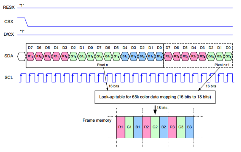
Note: The difference from the traditional SPI protocol is that the data line sent from the slave to the host is hidden because it only needs to be displayed.
RESX is the reset pin, it is pulled low when the module is powered on, usually set to 1;
CSX is the slave chip select pin, and the chip is enabled only when CS is low;
D/CX is the data/command control pin of the chip, when DC = 0 a command is written; when DC = 1, data is written
SDA is the data transmitted data, that is, RGB data;
SCL is the SPI communication clock pin.
For SPI communication, the data transmission has timing sequences involving clock phase (CPHA) and clock polarity (CPOL):
CPHA determines whether data is captured on the first or second clock edge. When CPHA = 0, data is captured on the first clock edge.
CPOL determines the idle level of the clock; CPOL = 0 means low.
From the diagram, it can be seen that when SCLK falls on the first edge, data transmission starts. One clock cycle transmits 8 bits, using SPI0, bitwise transmission, high bit first, and low bit last.
Dimensions
Working with ESP32-C3
Components Preparation
- ESP32-C3-Zero x1
- 0.71inch LCD Module x1
Hardware Connection
- 8PIN connector
| LCD Pin | ESP32C3 |
| VCC | 5V |
| GND | GND |
| DIN | GPIO7 |
| CLK | GPIO6 |
| CS | GPIO5 |
| DC | GPIO4 |
| RST | GPIO8 |
| BL | 3V3 |
Environment Setup
Download and install Arduino IDE
- Click to visit the official website, select the corresponding system and system bit to download

- Run the installer and install all by default
Install ESP32 development board
- To use ESP32 boards in Arduino IDE, first install the ESP32 Development Board
It is recommended to download and install ESP32_Arduino offline package (2.0.12 version recommended), and refer to Arduino board manager tutorial for the installation tutorial
Install libraries
- The necessary library files for this product are located in the Demo folder:
0.71inch-LCD-Module-Demo\ESP32-C3\libraries\, with library instructions detailed below
| Library Name | Description | Library Installation Requirements |
|---|---|---|
| TFT_eSPI | LCD driver library | "Install Offline” |
| LVGL | LVGL library | "Install Offline” |
- For library offline installation tutorial, please refer to Arduino library manager tutorial
Demos
- Download the Demo and unzip it
- Open the demos located at 0.71inch-LCD-Module-Demo\ESP32-C3\examples
| Demo | Description | Dependency Library |
|---|---|---|
| 1.Text_and_Number_Display | Text and nymber display | TFT_eSPI |
| 2.Shapes_on_Circular_Display | Drawing | TFT_eSPI |
| 3.Animated_Eye1 | Simulated eye style1 | TFT_eSPI |
| 4.Animated_Eye2 | Simulated eye style2 | TFT_eSPI |
| 5.Animated_Eye12 | Simulated eye styles1 and 2, displayed alternately | TFT_eSPI |
| 6.Image_Display | Display image | TFT_eSPI and LVGL |
| 7.Clock | Clock | TFT_eSPI and LVGL |
- Arduino project configuration:
Resources
Documents
Demo
FAQ
Support
Technical Support
If you need technical support or have any feedback/review, please click the Submit Now button to submit a ticket, Our support team will check and reply to you within 1 to 2 working days. Please be patient as we make every effort to help you to resolve the issue.
Working Time: 9 AM - 6 PM GMT+8 (Monday to Friday)


