Details
USB To UART Debugger Module for Raspberry Pi 5, Type-A Port, Onboard UART Connector, High Baud Rate Transmission, Multi Connection Methods, Multi System Support
UART Debugger Module for Raspberry Pi 5
Designed for Raspberry Pi 5
Stable transmission | Multi-device applicable | Multi-system compatible
Pi5 UART debugging
Suitable for Raspberry Pi 5, supports multiple Connection Methods
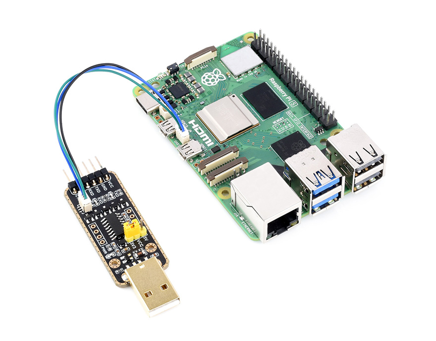
Connect to PI5 UART Debug Connector via SH1.0 3PIN cable
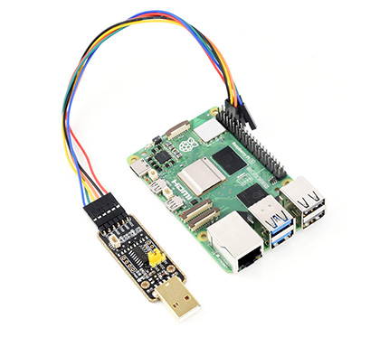
Connect onboard 6PIN header to PI5 GPIO UART Interface via 6PIN cable
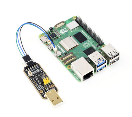
Connect onboard 6PIN header to PI5 UART Debug Connector via SH1.0 to 3PIN cable
Features at a glance
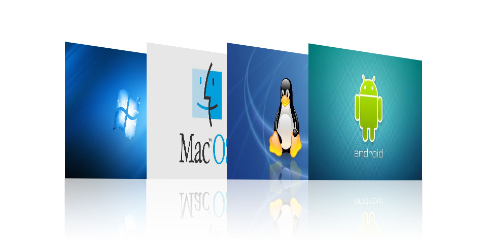
- Supports Mac, Linux, Android, Windows 7/8/8.1/10/11
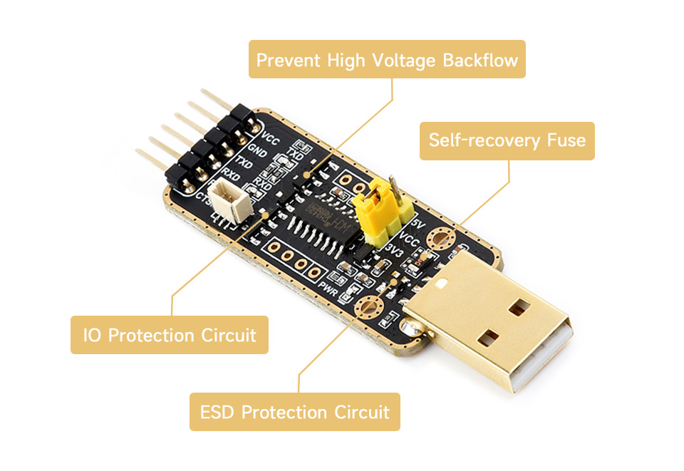
- Onboard self-recovery fuse and Transient Voltage Suppressor, anti-overcurrent and anti-overvoltage, anti-surge, anti-static, improves shock proof performance, stable and safe communication performance
- Onboard IO protection circuits, anti-surge, anti-static, stable and safe communication performance
- Onboard 3.3V and 5V TTL level switch pins for selecting TTL communication level
- Supports 3.3V/5V output (the module is powered by USB, and the onboard jumper should be shorted to 3.3V or 5V accordingly)
- Adopts double-sided black immersion gold process, which is durable and has a good look
Specifications
| HOST INTERFACE | USB |
|---|---|
| DEVICE INTERFACE | UART |
| COMMUNICATION RANGE | 50bps ~ 6Mbps |
| USB DEVICE INTERFACE | connector: USB Type-A; protection: self-recovery fuse, ESD protection |
| UART INTERFACE | connector: 6pin right-angle pinheader; 3pin connector protection: IO protection diode |
Multiple Protection Circuit, Safe And Stable
Onboard Self-recovery fuse And Transient Voltage Suppressor, Prevents Overcurrent And Overvoltage, Improves shock proof performance; Onboard IO Protection Circuit, Anti Surge, Anti-Static, Stable And Safe Communication Performance
Multiple systems support
Compatible with popular systems like Win7/8/8.1/10/11, Mac, Linux, Android...
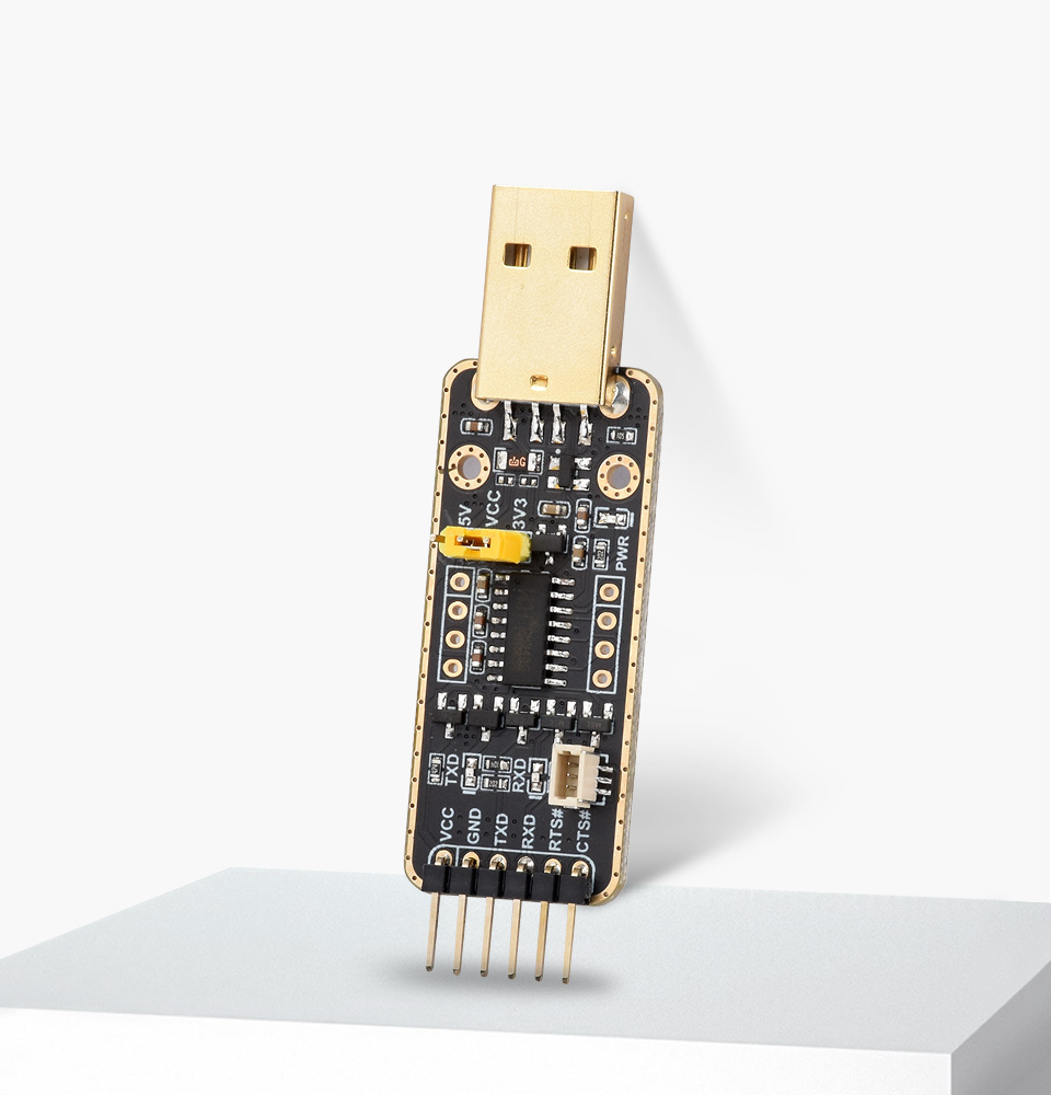
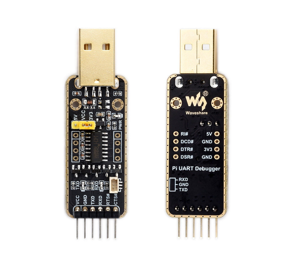
Interface Introduction

| Indicator description | |
|---|---|
| PWR | Power indicator, turns on when voltage is detected from USB interface |
| RXD | Receiving indicator, turns on when data is sent back from the device interface |
| TXD | Sending indicator, turns on when data is sent from USB |
Pinouts Definition

| VCC | 5V or 3.3V output for external device (configured by jumper) |
|---|---|
| GND | Ground |
| TXD | Connects to MCU.RXD |
| RXD | Connects to MCU.TXD |
| RTS# | Connects to MCU.CTS |
| CTS# | Connects to MCU.RTS |
Adopts double-sided black immersion gold process
Outline dimensions
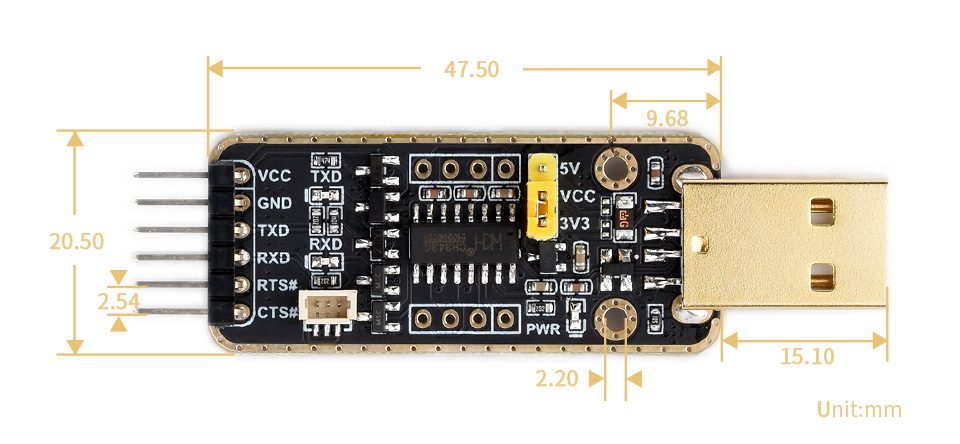

Weight: 0.014 kg
Quick Overview
- Pi UART Debugger x1
- 6-pin squid cable x1
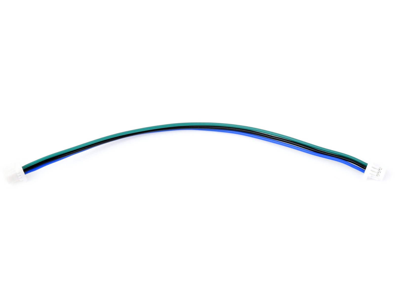
- SH1.0 connector to 3PIN cable ~100mm x1
- Dual SH1.0 connector 3PIN cable ~100mm x1
1
2

3

4