Details
Compatible with development environments such as Arduino-IDE, ESP-IDF, etc.
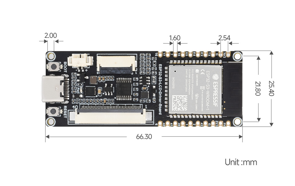
Based on ESP32-S3-WROOM-1-N8R8 module
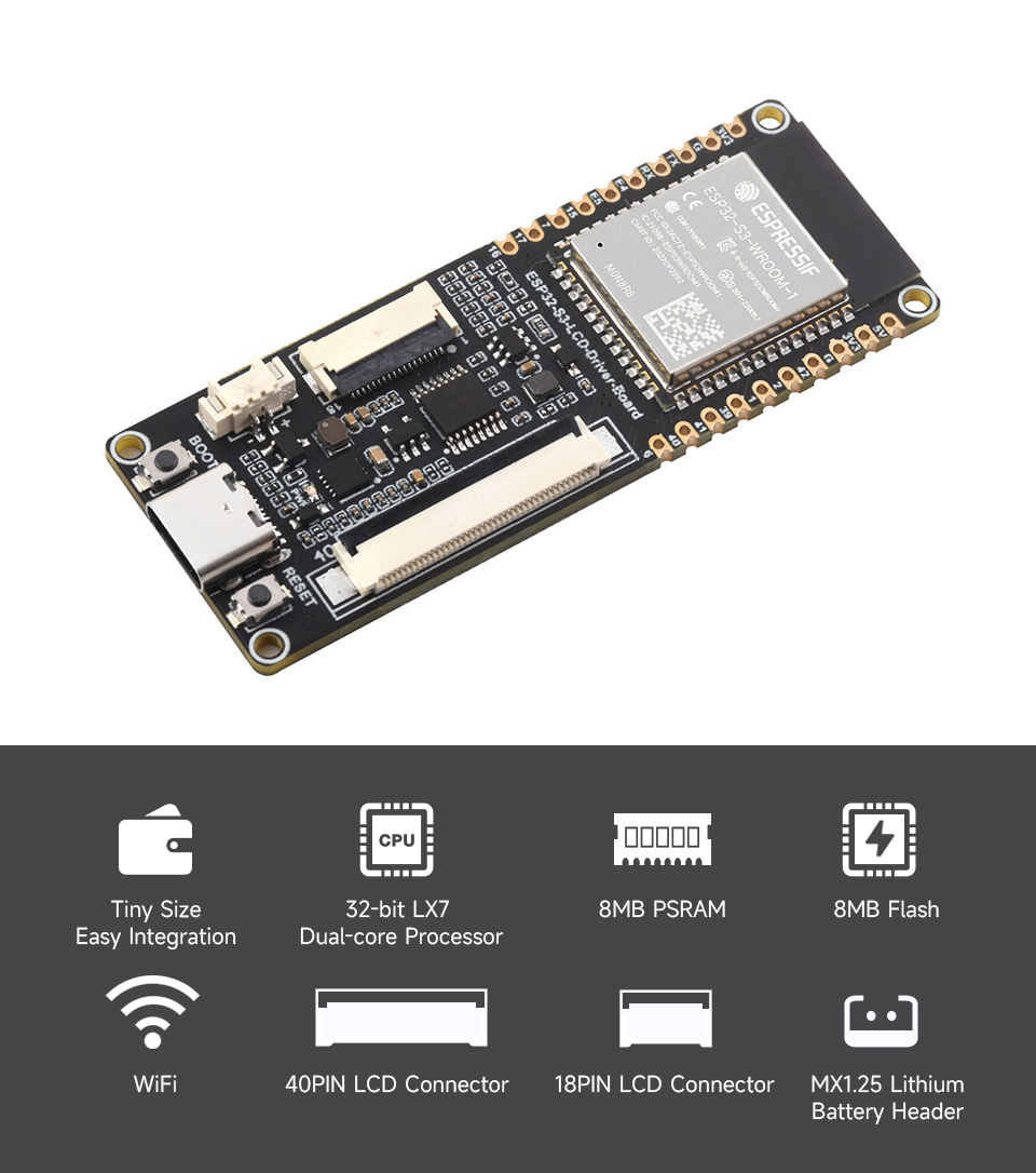
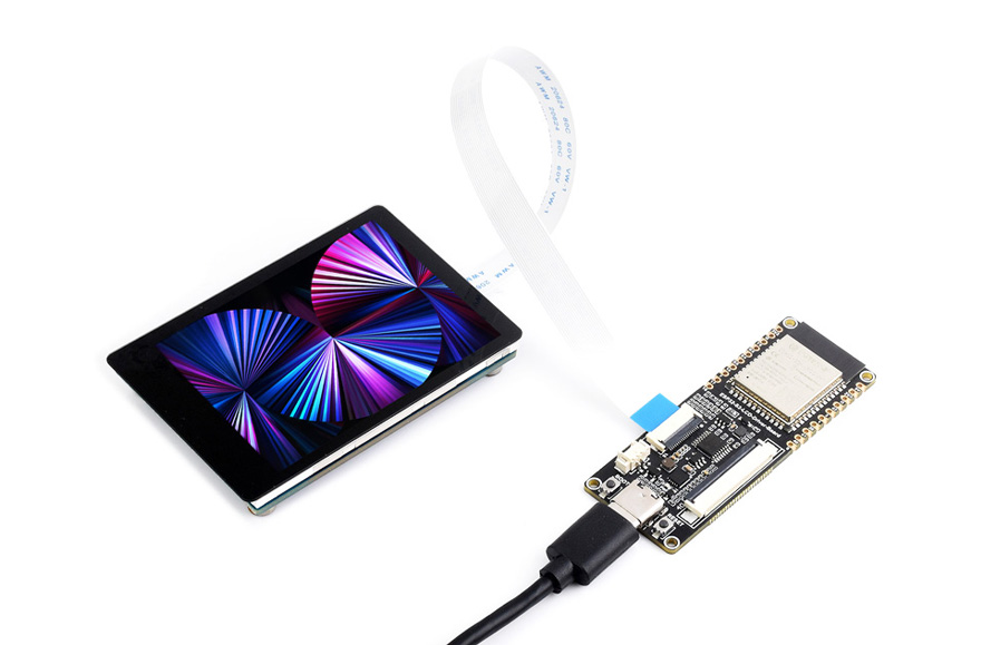
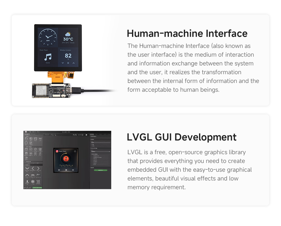
The ESP32-S3-LCD-Driver-Board is a compact-size microcontroller development board with 40Pin SPI+RGB and 18Pin SPI LCD connectors. Integrates high-capacity Flash and PSRAM, allows connecting to LCD screen through onboard two LCD connectors, can smoothly run GUI programs such as LVGL.
Adopts ESP32-S3-WROOM-1-N8R8 module, which is equipped with Xtensa 32-bit LX7 dual-core processor with 240MHz running frequency, built-in 512KB SRAM (TCM) and 8MB PSRAM; Onboard ETA6096 high-efficiency Lithium battery recharge manager and MX1.25 lithium battery header, adapting 20pin GPIO header which is compatible with 18Pin SPI screen. Supports expanding various peripheral devices and is easy to use.
You can choose Arduino-IDE, ESP-IDF, or other development environments in software so that you can easily and quickly get started and apply it to the product.
Key features:
- Adopts ESP32-S3-WROOM-1-N8R8 module with Xtensa 32-bit LX7 dual-core processor, capable of running at 240 MHz
- Integrated 512KB SRAM, 384KB ROM, 8MB PSRAM, 8MB Flash memory
- Integrated 2.4GHz Wi-Fi and Bluetooth LE dual-mode wireless communication, with superior RF performance
- Type-C connector, easier to use
- Onboard 40Pin SPI+RGB and 18Pin SPI LCD screen connector, strong compatibility and expandability
- Onboard Lithium battery recharge manager ETA6096 and MX1.25 lithium battery header
- Castellated module allows soldering direct to carrier boards
- Supports multiple low-power operating states, adjustable balance between communication distance, data rate and power consumption to meet the power requirements of various application scenarios
Onboard 18PIN connector, and reserved 20PIN GPIO header
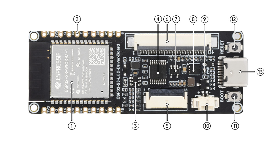
- ESP32-S3-WROOM-1-N8R8
Xtensa 32-bit LX7 dual-core processor - 20PIN header
- AP3032KTR
DC/DC boost chip - TCA9554PWR
GPIO expansion chip - 18PIN SPI display connector
- 40PIN SPI+RGB display connector
- ME6217C33M5G
800mA output, low dropout, high rejection rate
- ETA6096
high-efficiency Lithium battery recharge manager - Power indicator
- MX1.25 Lithium battery header
MX1.25 2P connector, for 3.7V Lithium battery, supports charging and discharging - BOOT button
press it before resetting to enter download mode - RESET button
- USB Type-C connector
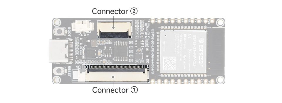
| Connector ①: 40PIN SPI+RGB | Connector ②: 18PIN PI | ||||||
|---|---|---|---|---|---|---|---|
| PIN NO. | SYMBOL | ESP32S3 Control pin | Funtion | PIN NO. | SYMBOL | ESP32S3 Control pin | Funtion |
| 1 | LEDA | - | backlight positive | 1 | VCC | 3.3V | LCD power input |
| 2,3 | LEDK | - | backlight negative | 2 | BL | 6 | backlight |
| 5 | VCI | 3.3V | I/O pins power supply | 3 | GND | GND | ground |
| 6 | RESET | EXIO3 | reset pin | 4 | SCLK | 1 | SPI CLK pin |
| 7,8 | NC | - | not connected | 5 | MOSI | 2 | SPI MOSI pin |
| 9 | SDA | 1 | SPI data signal pin | 6 | MISO | 42 | SPI MISO pin |
| 10 | SCL | 2 | SPI clock signal pin | 7 | DC | 41 | LCD data/command pin |
| 11 | CS | 42 | SPI chip select pin | 8 | RST | 40 | LCD reset pin |
| 12 | PCLK | 41 | pixel clock pin | 9 | CS' | 39 | LCD chip select pin |
| 13 | DE | 40 | control mode selection | 10 | NC | - | not connected |
| 14 | VS | 39 | Frame SYNC signal, vertical synchronizing input | 11 | NC | - | not connected |
| 15 | HS | 38 | Line SYNC signal, horizontal synchronizing input | 12 | RST' | 16 | touch reset pin |
| 16~21 | B0~B5 | NC, 5, 45, 48, 47, 21 | blue data input | 13 | SCL' | 7 | touch I2C clock pin |
| 22~27 | G0~G5 | 14, 13, 12, 11, 10, 9 | green data input | 14 | SDA' | 15 | touch I2C data pin |
| 28~33 | R0~R5 | NC, 46, 3, 8, 18, 17 | red data input | 15 | INT' | 17 | touch signal interrupt |
| 35 | TP-INT | 16 | touch signal interrupt | 16 | NC | - | not connected |
| 36 | TP-SDA | 15 | touch I2C data pin | 17 | NC | - | not connected |
| 37 | TP-SCL | 7 | touch I2C clock pin | 18 | NC | - | not connected |
| 38 | TP-RST | EXIO1 | touch reset pin | ||||
| 39 | TP-VCC | 3.3V | touch power supply | ||||
| 4,34,40 | GND | GND | ground | ||||
