Details
Waveshare USB Blaster V2 Download Cable, compatible with ALTERA USB Blaster FPGA/CPLD programmer, high-speed FT245+CPLD solution
Description
Waveshare USB Blaster V2 Download Cable, compatible with ALTERA USB Blaster FPGA/CPLD programmer. The USB Blaster Download Cable interfaces a USB port on a host computer to an Altera FPGA mounted on a printed circuit board. The cable sends configuration data from the PC to a standard 10-pin header connected to the FPGA. You can use the USB Blaster cable to iteratively download configuration data to a system during prototyping or to program data into the system during production.
It surpports most of the ALTERA FPGA/CPLD devices, Active Serial Configuration devices, Enhanced Configuration devices, and supports AS, PS, JTAG three download modes.
Key Features
- Hardware Solution
- High speed FT245+CPLD+244 solution, similar download speed as the original ALTERA USB Blaster, with the same operation.
- Download speed 1-3 times faster than other schemes, such as 68013 or C8051F.
- Performance
- Supports most of the ALTERA FPGA/CPLD devices, Active Serial Configuration devices, and Enhanced Configuration Devices.
- Supports AS, PS, JTAG three download modes.
- High-speed, stable, and internal FT245R+CPLD designed.
- Supports 1.2-5V programming voltage.
- Supports Nios II of embedded processor communication and debugging.
- Supported Softwares
- Quartus II integrated development environment.
- NIOS II IDE integrated development environment.
- NIOS II EDS integrated development environment.
- Supported Devices
Tested devices are listed below, including but not limited to:- CPLD: MAX3000, MAX7000A/B/S, MAX9000 and MAX II etc.
- FPGA: Stratix, Stratix II, Cyclone, Cyclone II, CycloneIII, ACEX 1K, APEX 20K and FLEX 10K etc.
- Active Serial Configuration Devices including: EPCS1, EPCS4, EPCS16 etc.
- Enhanced Configuration Devices including: EPC1, EPC4 etc.
- Connects to PC
- Computer connection via USB 2.0 interface.
- Connects to target board
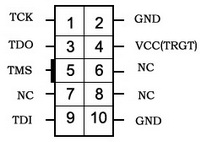
- Target board connection via JTAG, AS, PS interfaces. The figure 1, 2,and 3 below shows the header pinouts of different interfaces.
Figure 1. JTAG header pinout Figure 2. AS header pinout
 Figure 3. PS header pinout
- Red LED: Power indicator
- Green LED: Signal indicator, the LED is on while downloading/programming
LED Status
Downloads
Development resources:user manual, software, etc.
Wiki:
www.waveshare.com/wiki/USB_Blaster_V2


