Details
ATMEGA328P microcontroller development board, Arduino-compatible
R3 PLUS MCU development board
based on ATMEGA328P-AU
Compatible with the Arduino official R3 board

What's the differences
| R3 PLUS | Official R3 | Remarks | |
|---|---|---|---|
| Operating voltage | 5V/3.3V | 5V | Dual voltage level to support more shields |
| Reset | Lateral | Vertical | Lateral button is easier to use when connecting with shield |
| Bootloader switch | Yes | None | The board can be configured to run program immediately when power-up by the switch |
| USB connector | Micro USB | USB Type B | Micro connector is more commonly used, and shields won't be blocked anymore while connecting |
| DC jack | Low profile | Normal height | Shields won't be blocked anymore while connecting |
| Power output header | Yes | None | Providing 5V/3.3V power output OR common-grounding with other boards |
| 3.3V power output | 800mA Max | 150mA Max | R3 PLUS features higher driving capability |
| Oscillator | Crystal oscillator | Ceramic resonator | Crystal oscillator is suit for applications where accurate clock reference is required |
| ADC channel | 8 | 6 | CFG used as ADC6 by configuration, and ADC7 from the Reserved PIN |
| USB driver | Compatible with all main systems | Doesn't compatible with WIN7/WIN8 Express Edition | Driver will never failed to install thanks to the onboard FT232 |
| Firmware fixing | Supported | Not supported | Firmware can be fixed by using the onboard FT232, no extra programmer is needed |
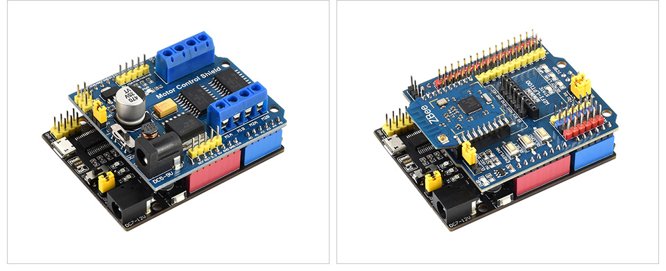
Connecting with Waveshare Shields
Connecting with Motor Control Shield and IO Expansion Shield

Connecting with Sorts of Sensors

What's On Board

- ATMEGA328P-AU
- AMS1117-3.3
3.3V voltage regulator - NCP1117ST50T3G
5V voltage regulator - FT232RL
USB to UART convertor - Arduino interface
compatible with standard Arduino interface with two additional analog inputs A6 (config the CFG), A7 - ICSP interface
- MICRO USB connector
for uploading program OR serial port debugging - Power output header
3.3V OR 5V, voltage level configured by the onboard power configuration switch, used as power output OR common-grounding with other boards
- FT232 pins
for burning Bootloader into the microcontroller - DC input
7V ~ 12V - Reset button
- Power indicator
- Serial port Rx/Tx indicator
- User LED
- 500mA fast auto-recovery fuse
- Power configuration
for configuring the operating voltage - Bootloader selection switch
- turn ON: the board will reset when power-up OR other USB devices were detected connecting to the PC
- turn OFF: the onboard program runs immediately when power-up, and the board will not reset when other USB devices were detected connecting to the PC
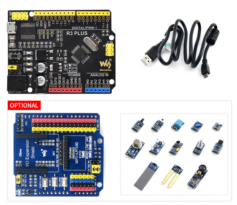
Optional development kit
development kit is also available for your convenience

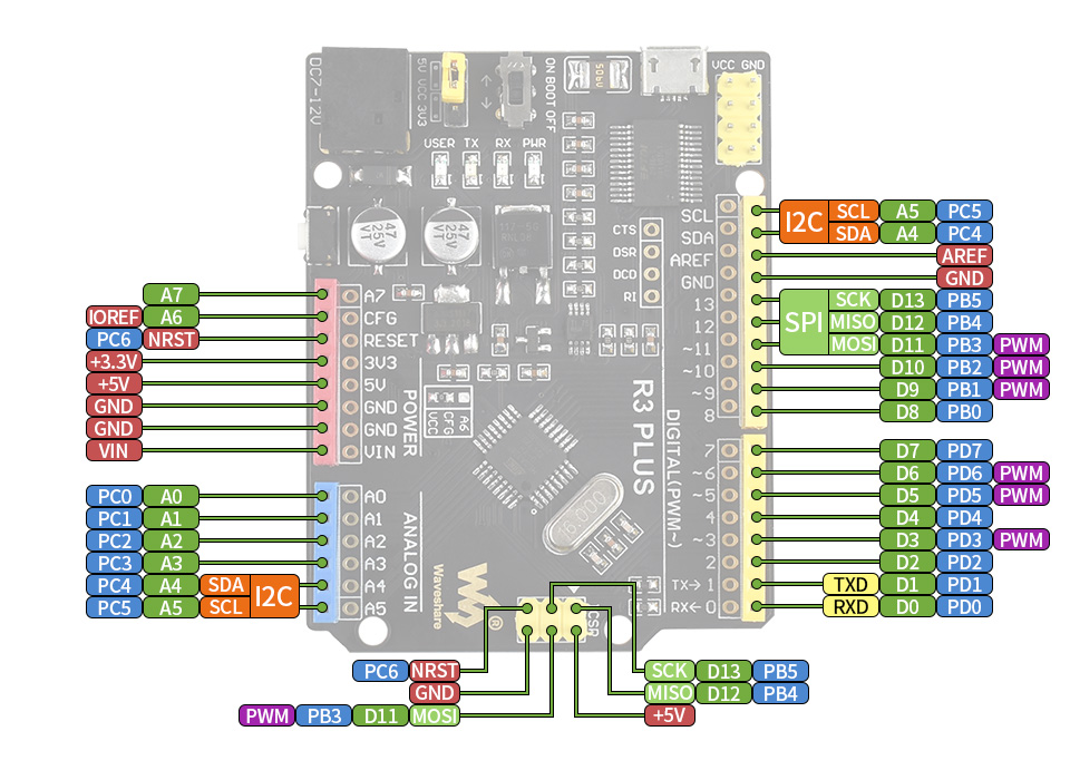
Pinout definition

Outline dimensions

Quick Overview
- R3-PLUS x1
- USB-A to micro-B cable x1
- OPTIONS IO Expansion Shield x1
- OPTIONS Sensors Pack x1


