Details
STM32 development board designed for the ST official tool STM32F0DISCOVERY, and integrates various standard interfaces, pretty easy for peripheral expansions.

Overview
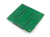
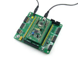
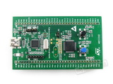
Open32F0-D is an STM32 development board designed for the ST official tool STM32F0DISCOVERY, which features the STM32F051R8T6 microcontroller onboard.
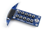
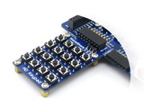
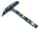
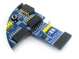
The Open32F0-D supports further expansion with various optional accessory boards for specific application. The modular and open design makes it the ideal for starting application development with STM32F0 series microcontrollers.
What's on the mother board

- STM32F0DISCOVERY socket: for easily connecting the STM32F0DISCOVERY
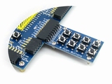
- 8I/Os + DAC + ADC interface: for connecting accessory boards such buttons, motors, AD/DA module etc.
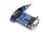
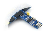
- USART2 interface: easily connects to RS232, RS485, USB TO 232, etc.
- SPI1 / SPI2 interface:easily connects to SPI peripherals such as DataFlash (AT45DBxx), SD card, MP3 module, etc.
- LCD connector: for connecting touch screen LCD
- USART1 interface: easily connects to RS232, RS485, USB TO 232, etc.
- I2C1 / I2C2 interface: easily connects to I2C peripherals such as I/O expander (PCF8574), FRAM (FM24CLxx), etc.
- I2S / I2C1 interface: easily connects to I2S peripherals such as audio module, etc.
- ONE-WIRE interface: easily connects to ONE-WIRE devices (TO-92 package), such as temperature sensor (DS18B20), electronic registration number (DS2401), etc.
- 5V/3.3V power input/output: usually used as power output, also common-grounding with other user board
- 5V DC jack
- MCU pins connector: all the MCU I/O ports are accessible on expansion connectors for further expansion
- SWD interface: for debugging/programming
- Joystick jumper
- short the jumper to connect the joystick to default I/Os used in example code
- open the jumper to connect the joystick to custom I/Os via jumper wires
- Boot mode switch: for configuring BOOT0 pin
- Power switch
- Power indicator
- Joystick: five positions
What's on the STM32F0DISCOVERY

- STM32F051R8T6 microcontroller featuring 64 KB Flash, 8 KB RAM in an LQFP64 package
- On-board ST-LINK/V2 with selection mode switch to use the kit as a standalone ST-LINK/V2 (with SWD connector for programming and debugging)
- Board power supply: through USB bus or from an external 5 V supply voltage
- External application power supply: 3 V and 5 V
- Four LEDs:
- LD1 (red) for 3.3 V power on
- LD2 (red/green) for USB communication
- LD3 (green) for PC9 output
- LD4 (blue) for PC8 output
- Two push buttons (user and reset)
- Extension header for all LQFP64 I/Os for quick connection to prototyping board and easy probing
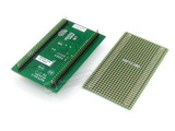
- An additional board is provided which can be connected to the extension connector for even easier prototyping and probing.
Photos
Note:
The Open32F0-D Standard does not include STM32F0DISCOVERY, nor any other accessory board.
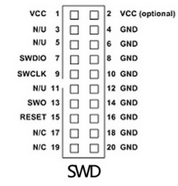
SWD interfaces
The figure below show the header pinout of SWD interface
Figure 1. SWD Header Pinout

Development Resources
- Related software (KEIL etc.)
- Demo code (examples in C, μC/OS-II)
- Schematic (PDF)
- STM32 development documentations (Datasheet etc.)


