Details
Designed for Raspberry Pi Compute Module 4


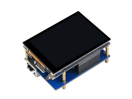
Touch screen expansion board only
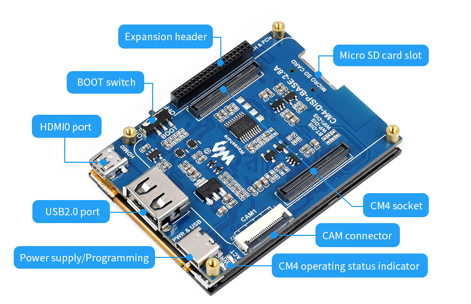
Allows directly attaching the CM4, providing 2.8″ IPS touch screen for all variants of CM4, also supports camera and video output.

Touch screen expansion board + interface expander
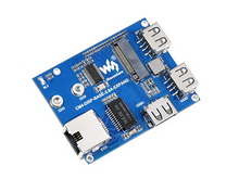
The touch screen expansion board and an additional interface expander, with Gigabit Ethernet port, M.2 slot for connecting communication module or SSD, and more USB ports.
2.8″ display with 5-point capacitive touch control, better touch experience from the Optical Bonding screen, together with 6H toughened glass panel, more safe to use


| CM4 socket | suitable for all variants of Compute Module 4 |
|---|---|
| USB | USB 2.0 × 1 |
| connector | MIPI CSI 22PIN 0.5mm camera connector |
| Display | 2.8″ Optical Bonding screen, 480 × 640 pixels, 5-point capacitive touch, toughened glass panel |
| Video | micro HDMI × 1, supports 4K 30fps output |
| Storage | MicroSD card socket for Compute Module 4 Lite (without eMMC) variants |
| Power input | 5V |

| Networking | Gigabit Ethernet RJ45 |
|---|---|
| M.2 M KEY, support NVME SSD or communication module | |
| USB | USB 2.0 × 3 |
Suitable for Raspberry Pi applications or other industrial occasions requiring multi-function peripherals


* Resources for different product may vary, please check the wiki page to confirm the actually provided resources.
| CM4 Base Board | Interface count and specifications | |||||||||||
|---|---|---|---|---|---|---|---|---|---|---|---|---|
| PoE | Gigabit ETH |
40PIN GPIO |
PCIe | USB① | DSI | HDMI | CSI | RTC | Fan Header |
Power Input |
Features | |
 NANO A |
√ | 2.0×1 | ×1 | 5V | CM4 sized | |||||||
 NANO B |
×1 | √ | 2.0×1 | ×1 | ×1 | ×1 | 5V | CM4 sized | ||||
 NANO C |
√ | 2.0×1 | ×1 | ×1 | ×1 | 5V | Onboard Camera | |||||
 mini Base A |
×1 | √ | M.2 M | 2.0×4 | ×1 | ×2 | ×2 | 5V | 5V | mini size | ||
 mini Base B |
×1 | √ | M.2 M | 2.0×4 | ×1 | ×2 | ×2 | √ | 5V | 5V | mini size | |
 mini Base C |
×1 | √ | M.2 M | 2.0×2 | ×1 | ×2 | √ | 5V | 5V | Dedicated 40PIN LCD Connector | ||
 Touch screen |
×1 | M.2 M | 2.0×4 | ×1 | ×1 | 5V | IPS screen | |||||
 Mini Dual Gigabit |
×2 | √ | 2.0×1 | 5V SH1.0 | 5V | dual ETH | ||||||
 Binocular camera |
×1 | √ | M.2 M | 2.0×4 | ×2 | 5V | dual 8MP cameras |
|||||
 4CH RS485 |
×1 | 2.0×2 | ×1 | ×2 | ×1 | 5V | 7-36V | dual ETH | ||||
 WIFI6 DUAL ETH |
×1 | √ | M.2 E | 2.0×3 | ×1 | ×2 | ×2 | ×1 | 5/12V | 7-36V | WIFI6 dual ETH | |
 Dual Gigabit ETH |
×2 | √ | 3.0×3 | ×1 | ×2 | ×2 | √ | 5/12V | 7-36V | |||
 IoT Dual Gigabit ETH |
×2 | √ | 3.0×2 | ×1 | ×2 | ×2 | √ | 5/12V | 5V | 5G/4G support | ||
 IoT Base |
√ | ×1 | Gen2×1 | 2.0×2 | ×2 | ×2 | ×2 | √ | 5/12V | 7-36V | 5G/4G support RS232 RS485 ADC |
|
 PoE Base (B) |
√ | ×1 | √ | Gen2×1 | 2.0×4 | ×2 | ×2 | ×2 | √ | 5/12V | 5V | RS232 RS485 |
 PoE UPS Base |
√ | ×1 | √ | M.2 M | 2.0×4 | ×1 | ×2 | ×2 | √ | 5/12V | 7-36V | UPS |
 PoE Base |
√ | ×1 | √ | 3.0×4 | ×2 | ×2 | ×2 | √ | 5/12V | 7-36V | ||
 Raspberry Pi official |
② | ×1 | √ | Gen2×1 | 2.0×4 | ×2 | ×2 | ×2 | √ | 12V | 12V | |
 Wireless base |
×1 | M.2 B / Mini-PCIe |
2.0×3 | ×1 | ×1 | √ | 5/12V | 5V or 7-36V |
5G/4G support RS485 CAN rail-mount |
|||
 UPS Wireless base |
×1 | M.2 B | 2.0×3 | ×1 | ×1 | √ | 5/12V | 5V or 7-36V |
With UPS 5G/4G support RS485 CAN rail-mount |
|||
 NAS Mini Computer |
×2 | √ | M.2 M×2/ Mini-PCIe |
3.0×2 | ×2 | ×2 | √ | 5V | dual M.2 M KEY slots | |||
 5″ touch screen |
② | ×1 | √ | M.2 M | 2.0×4 | ×1 | ×2 | √ | 5/12V | 5V | ||
 7″ all-in-one |
×1 | M.2 M | 2.0×4 | used | ×1 | used | √ | 5/12V used |
7-36V | touch screen camera speaker |
||
 13.3″ all-in-one |
×1 | 2.0×2 | 12V | HD touch screen | ||||||||
 13.3″ Magic Mirror |
×1 | 2.0×2 | 12V | HD screen, Speech Assistant |
||||||||
| Note | ① USB 3.0 is equivalent to USB 3.2 Gen1 ② There's PoE header only on the Raspberry Pi official IO board without PoE circuit, that means additional PoE module is required for the official IO board to enable PoE feature. Unless otherwise specified, the PoE feature here stands for integrating 802.3af-compliant PoE circuit (5V/2.5A). |
|||||||||||


