Details
LPC4337JBD144 MCU core board
Features
Core4337 is an LPC MCU core board that features an LPC4337JBD144 device as the microcontroller, supports further expansion.
- integrated MCU basic circuit, such as clock circuit, USB power management, USB interface, etc.
- all the I/O ports are accessible on the pin headers
- onboard JTAG/SWD programming/debugging interface
- 2.0mm header pitch design, suitable for being plugged-in your application system
What's On Board
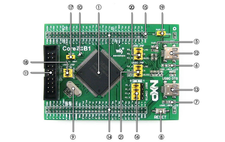
- LPC4337JBD144:the LPC ARM Cortex-M4/M0 dual-core microcontroller:
- Core: Cortex-M4 processor, 204MHz Max
- Core: Cortex-M0 coprocessor, 204MHz Max
- Package: LQFP144
- I/Os: 83
- Memories: FLASH total 1M, SRAM total 136kB, ROM 64kB, E2PROM 16kB, OTP memory 64 bit
- Interfaces:
- 1 x SPIFI, 1 x 10/100T MAC
- 1 x High-speed USB2.0 Host/Device/OTG
- 1 x High-speed USB 2.0 Host/Device
- 1 x 550 UART, 3 x 550 USART, 1 x IrDA
- 2 x CAN 2.0, 2 x SSP, 1 x SPI, 1 x Fast-mode Plus I2C
- 1 x standard I2C-bus, 2 x I2S, 1 x EMC, 1 x SD/MMC
- 1 x PWM, 1 x QEI, 1 x 10-bit DAC, 2 x 10-bit ADC
- AMS1117-3.3 (on bottom side), 3.3V voltage regulator
- LM3625-H (on bottom side), USB power management device
- QSPI FLASH solder pads (on bottom side), for soldering external Flash if required
- Power indicator
- USB1 VBUS LED
- USB0 VBUS LED
- Reset button
- 12M crystal oscillator
- 32.768K crystal, for internal RTC with calibration
- JTAG/SWD interface: for debugging/programming
- USB1 interface:
- Device mode: communicating with computer
- Host mode: communicating with USB devices (such as USB Flash Drive) through an adapter cable
- USB0 interface, features USB OTG function
- MCU pins expander, VCC, GND and all the I/O ports are accessible on expansion connectors for further expansion
- 5Vin power input, power the core board from external supply (while working on USB HOST/OTG mode, a 5V power input is required)
- BOOT configuration
- VBAT selection jumper
- short the jumper to use system power supply
- open the jumper to connect the VBAT to external power supply, such as battery
- USB PWR OUT jumper
- short the jumper: powered from USB1 VBUS (it's possible to provide power to the mother board via the 5V pin)
- open the jumper: powered from the mother board
- USB1 jumper
- short the jumper when using USB1
- open the jumper to disconnect from I/O port
- USB0 jumper
- short the jumper when using USB1
- open the jumper to disconnect from I/O port
Photos


Note: Debugger and Mother board in the photos are NOT included in the price.
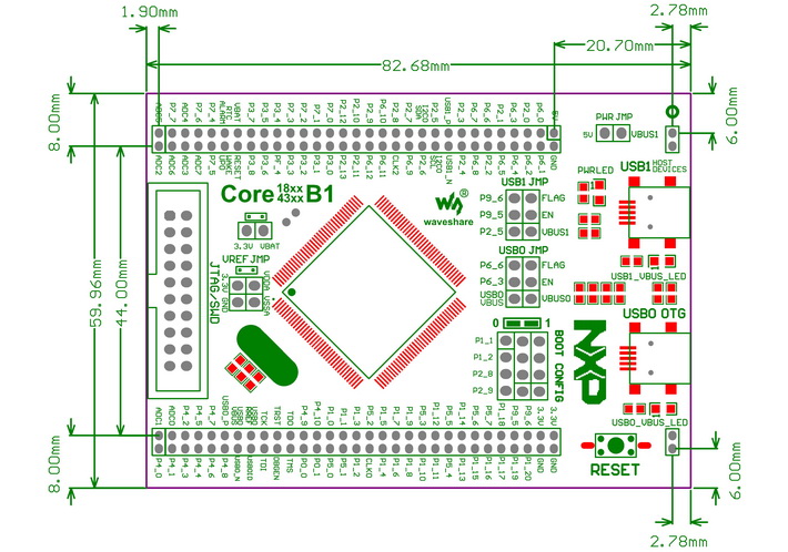
Dimensions
Development Resources
- Related software (KEIL etc.)
- Examples in C
- Schematic (PDF)
- LPC Cortex-M3/M4 development documentations
Weight: 0.05 kg
Quick Overview
- Core4337 LPC MCU board x1
- USB type A plug to mini-B plug cable x1
- Software CD x1
1
2

3

