PCF8591 AD DA Board
| ||
Overview
The PCF8591 AD DA Board features an 8-bit A/D Converter & D/A Converter PCF8591 with four analog inputs, one analog output, and a serial I2C-bus interface.
The PCF8591 AD DA Board features I2C pinheader on one side and an I2C connector on the opposite side. Hence, it's more flexible to connect the board to your development system. The board also supports I2C cascading, allowing the use of multi modules connected to the I2C bus at the same time by connecting the pinheader and connector.
Features
- Chip: PCF8591
- Working voltage: 3.3V/5V
- Max transfer rate: 11.1KHz
- ADC precision: 8 bits
- DAC precision: 8 bits
- ADC channel: 4
- DAC channel: 1
- Interface: I2C
Pinouts
| PIN | Description |
| VCC | 3.3V/5V |
| GND | Power ground |
| SDA | I2C data input |
| SCL | I2C clock pin |
Raspberry Pi
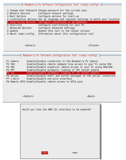
Enable I2C Interface
Open a terminal and run the following commands:
sudo raspi-config
Choose Interfacing Options -> I2C -> Yes.
Reboot Raspberry Pi:
sudo reboot
Install Library
If you use bookworm system, only the lgpio library is available, bcm2835 and wiringPi libarary cannot be installed or used. Please note that the python library does not need to install, you can directly run the demo.
BCM2835
#Open the Raspberry Pi terminal and run the following command
wget http://www.airspayce.com/mikem/bcm2835/bcm2835-1.71.tar.gz
tar zxvf bcm2835-1.71.tar.gz
cd bcm2835-1.71/
sudo ./configure && sudo make && sudo make check && sudo make install
# For more, you can refer to the official website at: http://www.airspayce.com/mikem/bcm2835/
WiringPi
#Open the Raspberry Pi terminal and run the following command
cd
sudo apt-get install wiringpi
#For Raspberry Pi systems after May 2019 (earlier than that can be executed without), an upgrade may be required:
wget https://project-downloads.drogon.net/wiringpi-latest.deb
sudo dpkg -i wiringpi-latest.deb
gpio -v
# Run gpio -v and version 2.52 will appear, if it doesn't it means there was an installation error

# Bullseye branch system using the following command:
git clone https://github.com/WiringPi/WiringPi
cd WiringPi
. /build
gpio -v
# Run gpio -v and version 2.70 will appear, if it doesn't it means there was an installation error
lgpio
wget https://github.com/joan2937/lg/archive/master.zip
unzip master.zip
cd lg-master
sudo make install
#for more details, you can refer to https://github.com/gpiozero/lg
Python3
#python3
sudo apt-get update
sudo apt-get install python3-pip
sudo apt-get install python3-pil
sudo apt-get install python3-numpy
sudo pip3 install RPi.GPIO
sudo pip3 install spidev
Download examples
Open a terminal of the Raspberry Pi
sudo apt-get install p7zip-full -y
sudo wget  https://files.waveshare.com/upload/1/17/PCF8591-Code.7z
7z x PCF8591-Code.7z -O./PCF8591-Code
cd PCF8591-Code/RaspberryPi/
Hardware connection
| PCF8591 | Raspberry Pi | Description |
| Board order | ||
| VCC | 5V | Power input |
| GND | GND | Power ground |
| SDA | 3 | I2C data input |
| SCL | 5 | I2C clock pin |
Run examples
C examples
cd ~/PCF8591-Code/RaspberryPi/
cd wiringPi
sudo make clean
sudo make
sudo ./test
Python example
cd ~/PCF8591-Code/RaspberryPi/
cd python
sudo python3 PCF8591.py
Expected result
The AD values of four channels are printed.
The STM32 examples are based on the STM32F103RBT6 and the STM32H743. The connection provided below is based on the STM32F103RB. If you need to use other STM32 boards, you may need to change the hardware connection and port the code yourself.
STM32
Hardware connection
| PCF8591 | STM32 | Description |
|---|---|---|
| VCC | 3.3V | Power input |
| GMD | GND | Power ground |
| SDA | PB9 | I2C data input |
| SCL | PB8 | I2C clock pin |
Examples
The examples are developed based on the HAL libraries. Download the Demo codes archive to your PC. Unzip and find the STM32 project from PCF8591-Code\STM32\STM32F103RB\MDK-ARM.
- Open the PCF8591 AD DA Board.uvprojx file by Keil.
- Create a project.
- Program the project to your STM32 board.
- Connect the UART1 of your STM32 board to the PC and check the serial data with SSCOM software.
The Arduino example is written for the Arduino UNO. If you want to connect it to other Arduino boards, you may need to change the connection.
Arduino
Hardware connection
| PCF8591 | Arduino | Description |
|---|---|---|
| VCC | 5V | Power input |
| GMD | GND | Power ground |
| SDA | SDA | I2C data input |
| SCL | SCL | SCL clock pin |
Examples
- Download the demo codes to your PC and unzip them.
- Install the Arduino IDE in your PC.
- Go into PCF8591-Code/Arduino/PCF8591.
- Run the PCF8591.ino file.
- Select the correct Board and the Port.
- Build the project and upload it to the board.
- Open the serial monitor of the Arduino IDE or the SSCOM software and check the serial data.
Resources
Beware of knock-offs
Please note that we've found some poor copies of this item in the market. They are usually made of inferior materials and shipped without any testing.
You might be wondering if the one you're watching or you've purchased in other non-official stores is original, feel free to contact us.
Support
Technical Support
If you need technical support or have any feedback/review, please click the Submit Now button to submit a ticket, Our support team will check and reply to you within 1 to 2 working days. Please be patient as we make every effort to help you to resolve the issue.
Working Time: 9 AM - 6 PM GMT+8 (Monday to Friday)


